Gas transmission device and gas transmission system

A gas transmission and air technology, which is applied in the field of gas transmission, can solve the problems of inability to mix and evenly flow the gas, achieve good dust removal and dehumidification functions, strong swirl effect, and simple structure

Pending Publication Date: 2021-01-15
SHANGHAI BIXIUFU ENTERPRISE MANAGEMENT CO LTD
View PDF0 Cites 0 Cited by
  • Summary
  • Abstract
  • Description
  • Claims
  • Application Information

AI Technical Summary

Problems solved by technology

[0003] In view of the shortcomings of the prior art described above, the purpose of the present invention is to provide a gas transmission device and a gas transmission system, which are used to solve the problem that the gas transmission system in the prior art cannot perform better uniform mixing and flow of gas, etc.

Method used


Image

  • Gas transmission device and gas transmission system
  • Gas transmission device and gas transmission system
  • Gas transmission device and gas transmission system

Examples


Embodiment Construction

[0036] Embodiments of the present invention are described below through specific examples, and those skilled in the art can easily understand other advantages and effects of the present invention from the content disclosed in this specification. The present invention can also be implemented or applied through other different specific implementation modes, and various modifications or changes can be made to the details in this specification based on different viewpoints and applications without departing from the spirit of the present invention. It should be noted that, in the case of no conflict, the following embodiments and features in the embodiments can be combined with each other.

[0037] It should be noted that the diagrams provided in the following embodiments are only schematically illustrating the basic ideas of the present invention, and only the components related to the present invention are shown in the diagrams rather than the number, shape and number of componen...


PUM


Abstract

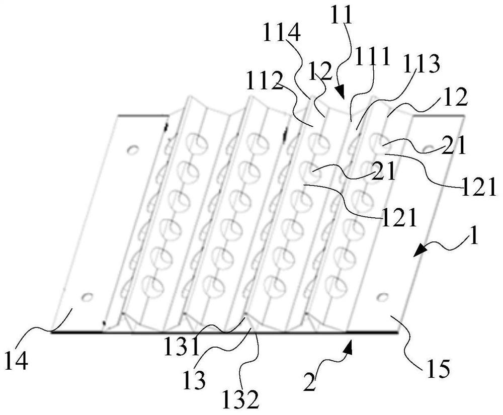
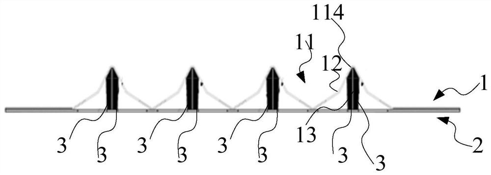
The invention provides a gas transmission device and a gas transmission system. The gas transmission device comprises a front plate and a back plate arranged at the bottom of the front plate, whereinthe front plate is of a concave-convex alternating structure, first grooves are formed in the concave-convex alternating structure, and the bottoms of the first grooves are adjacent to the back plate;at least one side faces of at least a part of the first grooves are provided with second grooves bent in a direction close to the back plate; the second grooves are provided with a plurality of frontplate holes; the back plate is provided with back plate holes corresponding to the front plate holes; and the front plate holes and the corresponding back plate holes form fluid channels. The gas transmission device disclosed by the invention is simple in structure and easy to engineer, good in uniform mixing and flow equalizing effects, strong in rotational flow effect, and good in dust removaland dehumidification functions.

Description

technical field [0001] The gas transmission field of the present invention particularly relates to a gas transmission device and a gas transmission system. Background technique [0002] The uniform flow structure has been widely concerned in the gas delivery system, and it is used for the uniform flow of gas through the channel. On the one hand, the traditional homogeneous flow structure is complex, resulting in high system pressure loss and high energy consumption requirements; Small processing capacity, easy to scale. Contents of the invention [0003] In view of the shortcomings of the prior art described above, the purpose of the present invention is to provide a gas transmission device and a gas transmission system, which are used to solve the problem that the gas transmission system in the prior art cannot perform better uniform mixing and flow of gas, etc. . [0004] In order to achieve the above object and other related objects, the present invention provides a ...

Claims


Application Information

Patent Timeline
Patent Type & Authority Applications(China)
IPC IPC(8): B01D45/16B01D45/02
CPCB01D45/02B01D45/16
Inventor 汤红池唐万福奚勇
Owner SHANGHAI BIXIUFU ENTERPRISE MANAGEMENT CO LTD
Why Eureka
Try Eureka