
Roof gluing equipment and roof gluing method

A kind of equipment and gluing technology, applied in the direction of roofing, tools for roof engineering, devices for coating liquid on the surface, etc., can solve the problems affecting the bonding and installation quality or installation strength of solar panels, the length and thickness of the glue strips are not the same, Problems such as numbness and soreness of the operator's legs, to achieve the effect of improving the working efficiency of the glue, keeping the glue thickness uniform, and the glue pushing action stably

Active Publication Date: 2021-01-15
CHENGDU GREATER AUTOMATION EQUIP CO LTD
View PDF22 Cites 3 Cited by
  • Summary
  • Abstract
  • Description
  • Claims
  • Application Information

AI Technical Summary

Problems solved by technology

[0002] Solar power generation, as a clean and pollution-free power generation technology, has been more and more widely used. Many factories have begun to install solar power panels on the roofs of factories. This kind of installation of solar power panels requires first coating structural adhesive on the roof, and then applying solar energy to the roof. The panels are installed on the roof, and after the glue dries, the solar panel is fixed on the roof with structural glue. The traditional way of gluing is to manually hold a hand-held glue gun and squat on the roof for manual gluing. Due to the large roof area , It takes a long time to manually apply glue, and the operator is prone to numbness and soreness in the legs and hands when squatting for a long time, and considering that the glued strips are not installed in time and the solar panels will be dried, which will affect the subsequent installation, so it is necessary Many people are working on the roof at the same time, and different operators have different glue application proficiency, and the glue strips are different in length, thickness, or even twisted, which will affect the bonding and installation quality of solar panels or installation. strength

Method used


Image

  • Roof gluing equipment and roof gluing method
  • Roof gluing equipment and roof gluing method
  • Roof gluing equipment and roof gluing method

Examples


Embodiment

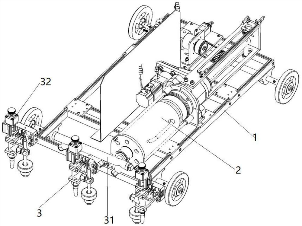
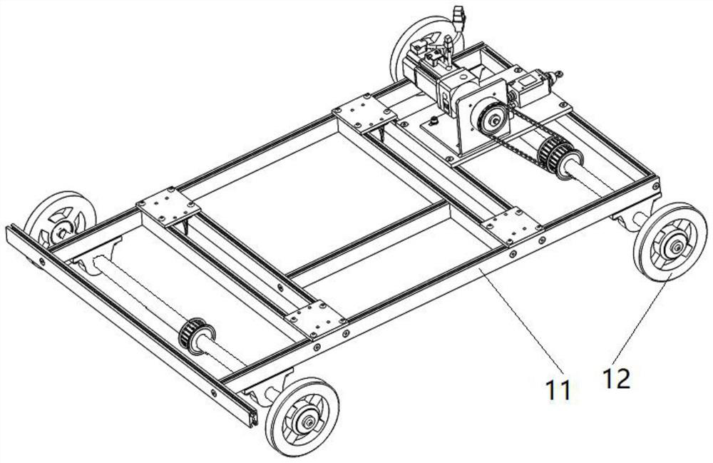
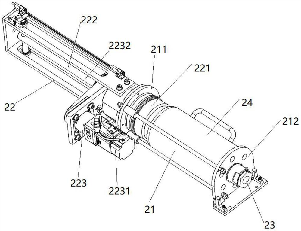
[0036] like Figure 1-Figure 4 As shown, a roof gluing equipment includes a traveling mechanism 1, a glue squeezing mechanism 2 and a gluing mechanism 3;

[0037] The running mechanism 1 comprises a vehicle frame 11 and road wheels 12 arranged on both sides of the vehicle frame 11. The vehicle frame 11 is provided with a gluing mechanism 2 along one end of its advancing direction, and the vehicle frame 11 is provided with a rubber extrusion mechanism 2. Link to each other with gluing mechanism 3;

[0038] The rubber extruding mechanism 2 includes a rubber barrel clamping mechanism 21 and a rubber pushing mechanism 22. The rubber barrel clamping mechanism 21 includes a rear baffle 211 and a front baffle 212 arranged in sequence along the advancing direction of the vehicle frame 11, and the front baffle 212 is far away from the rear baffle. One end of the baffle 211 is provided with a glue outlet 23, and the side of the rear baffle 211 facing away from the front baffle 212 is p...


PUM


Abstract

The invention discloses roof gluing equipment and a roof gluing method. The roof gluing equipment comprises a walking mechanism, a glue squeezing mechanism and a gluing mechanism, wherein the walkingmechanism is provided with the glue squeezing mechanism, the glue squeezing mechanism is connected with the gluing mechanism, the glue squeezing mechanism comprises a glue barrel clamping mechanism and a glue pushing mechanism, and the gluing mechanism comprises a plurality of gluing valves. The walking mechanism walks on a roof to drive the glue extruding mechanism and the gluing mechanism to move on the roof, the glue extruding mechanism is used for squeezing glue and squeezing materials into the gluing mechanism while the walking mechanism moves, and the gluing mechanism is used for gluing,so that the manual gluing difficulty can be effectively reduced, and the gluing quality and the gluing efficiency are improved.

Description

technical field [0001] The invention relates to the field of building construction, in particular to a roof gluing equipment. Background technique [0002] Solar power generation, as a clean and pollution-free power generation technology, has been more and more widely used. Many factories have begun to install solar power panels on the roofs of factories. This kind of installation of solar power panels requires first coating structural adhesive on the roof, and then applying solar energy to the roof. The panels are installed on the roof, and after the glue dries, the solar panel is fixed on the roof with structural glue. The traditional way of gluing is to manually hold a hand-held glue gun and squat on the roof for manual gluing. Due to the large roof area , It takes a long time to manually apply glue, and the operator is prone to numbness and soreness in the legs and hands when squatting for a long time, and considering that the glued strips are not installed in time and t...

Claims


Application Information

Patent Timeline
Patent Type & Authority Applications(China)
IPC IPC(8): B05C5/02B05C11/10B05C11/00B05D1/26E04D15/00
CPCB05C5/02B05C11/10B05C11/1002B05C11/00B05D1/265E04D15/00Y02E10/50
Inventor 刘阳界张杰宿靖亭冯永生何懋
Owner CHENGDU GREATER AUTOMATION EQUIP CO LTD
Learn More