
Mechanical arm machining track correction method based on three-dimensional vision

A processing trajectory, three-dimensional vision technology, applied in the direction of manipulators, program control manipulators, manufacturing tools, etc., can solve problems affecting product processing quality, time-consuming and labor-intensive, economic losses, etc., to reduce the amount of teaching, improve quality, and improve The effect of automation

Inactive Publication Date: 2021-01-15
HUNAN UNIV
View PDF5 Cites 9 Cited by
  • Summary
  • Abstract
  • Description
  • Claims
  • Application Information

AI Technical Summary

Problems solved by technology

Before traditional industrial robots perform repetitive tasks, operators need to program the path and trajectory of the robot's movement point-to-point. This method is more intuitive, but time-consuming and labor-intensive
In addition, if the position of the workpiece changes, the teaching point needs to be recalibrated. Even if the position change is relatively small and difficult to detect (for example, 2-3mm), the deviation will directly affect the final product processing quality and cause economic losses.

Method used


Image

  • Mechanical arm machining track correction method based on three-dimensional vision
  • Mechanical arm machining track correction method based on three-dimensional vision
  • Mechanical arm machining track correction method based on three-dimensional vision

Examples


Embodiment

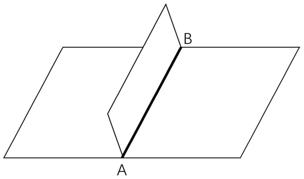
[0044] In this embodiment, the workpiece to be welded with a straight line fillet weld is used for illustration, and its schematic diagram is as follows figure 1 As shown, the red line AB marked in the figure is the weld:

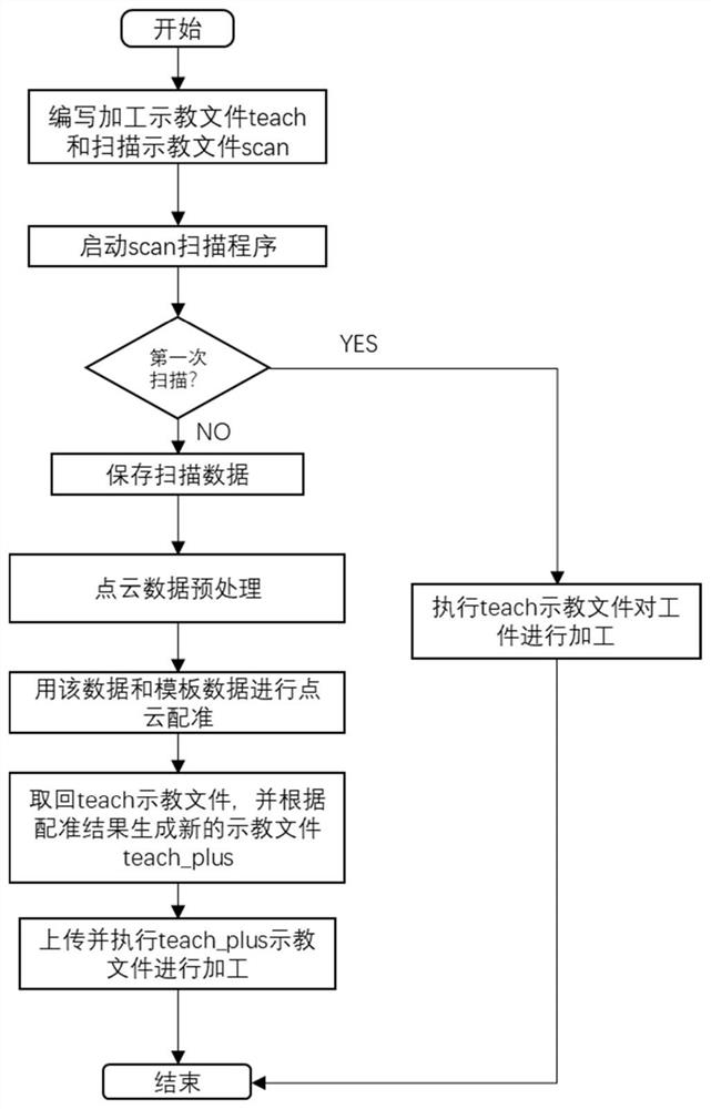
[0045] like figure 2 As shown, a method for correcting the machining trajectory of a manipulator based on three-dimensional vision, the method includes the following steps:

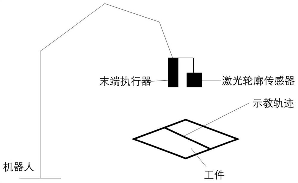
[0046] (a) Through the teaching pendant, the teaching program teach of robot workpiece processing and the teaching program scan of scanning are written point-to-point and saved (the name of the teaching program can be modified according to the needs of the user). The teaching program teach and scan are written by the operator. The teaching point of the processing trajectory is saved in the teach teaching file, and the operator writes the teaching program according to the processing trajectory of the workpiece to be processed; the scan teaching program scan needs to scan the workpiece...


PUM


Abstract

The invention discloses a mechanical arm machining track correction method based on a three-dimensional vision. The method comprises the following steps: 1, compiling two teaching programs by a demonstrator, one teaching program being used for sensor scanning to acquire data, and the other teaching program being used for guiding a robot to perform machining work along a machining track; S2, starting a scanning program: if scanning is the first scanning, directly executing a processing teaching program, and if scanning is not the first scanning, acquiring point cloud data and registering the point cloud data with template point cloud data, and calculating translation vectors and rotation matrixes of two point cloud data sets; S3, correcting the teaching point positions in a teaching file byutilizing the translation vectors and the rotation matrixes calculated in the step S2 to generate a new teaching file, and transmitting the new teaching file to a robot controller; and S4, executing,by the robot, the corrected teaching file to complete machining.

Description

technical field [0001] The invention belongs to the field of industrial application of manipulators, in particular to a three-dimensional vision-based machining trajectory correction method of manipulators. Background technique [0002] With the advancement of technology and the rapid development of sensor precision, the visual perception ability of robots has become an important indicator to measure the degree of intelligence of robots. The continuous progress of three-dimensional vision makes the visual perception ability of the robot stronger and stronger. It has the advantages of non-contact, high precision and high efficiency. Before traditional industrial robots perform repetitive tasks, the operator needs to program the path and trajectory of the robot's movement point-to-point. This method is more intuitive, but time-consuming and labor-intensive. In addition, if the position of the workpiece changes, the teaching point needs to be recalibrated. Even if the position...

Claims


Application Information

Patent Timeline
IPC IPC(8): B25J9/16
CPCB25J9/1664
Inventor 孙炜苑河南
Owner HUNAN UNIV
Learn More