Injection molding machine

An injection molding machine and injection molding technology, applied in the field of injection molding equipment, can solve the problems of heavy mold quality, laborious, inconvenient mold replacement, etc., and achieve the effect of reducing the use of manpower and reducing resistance

Pending Publication Date: 2021-01-15
上海莎安精密注塑有限公司
View PDF6 Cites 1 Cited by
  • Summary
  • Abstract
  • Description
  • Claims
  • Application Information

AI Technical Summary

Problems solved by technology

However, due to the heavy weight of medium-sized and slightly larger molds, it is laborious to carry them directly by hand, and it is inconvenient to replace the molds

Method used


Image

  • Injection molding machine
  • Injection molding machine
  • Injection molding machine

Examples


Embodiment

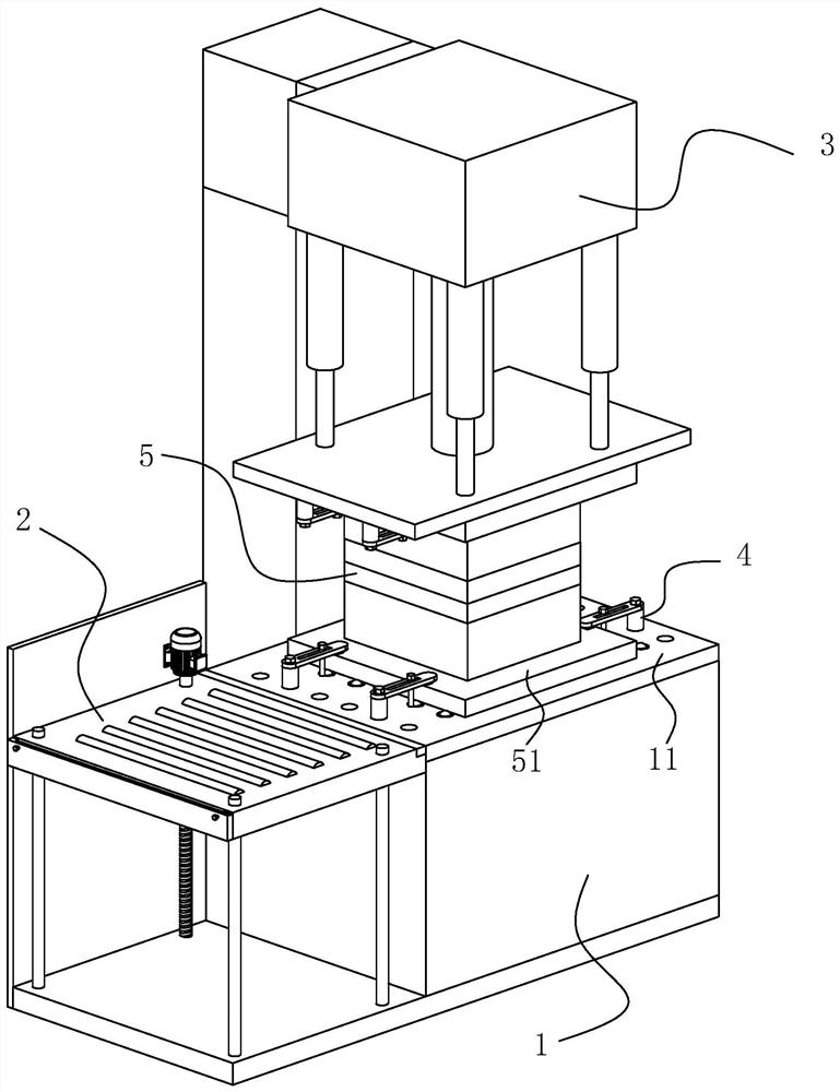
[0032] Embodiment: a kind of injection molding machine, see figure 1 , including a frame 1 , a feeding device 2 arranged on one side of the frame 1 , an injection molding device 3 arranged on the top of the frame 1 , and a pressing assembly 4 arranged on the frame 1 . Below the injection molding device 3 is a workbench 11 , and the mold 5 is located between the injection molding device 3 and the workbench 11 . The injection molding device 3 can drive the upper mold of the mold 5 to open and close the mold and inject plastic in a molten state into the mould. The pressing assembly 4 compresses the connecting plates 51 at the bottom and top of the mold 5 .

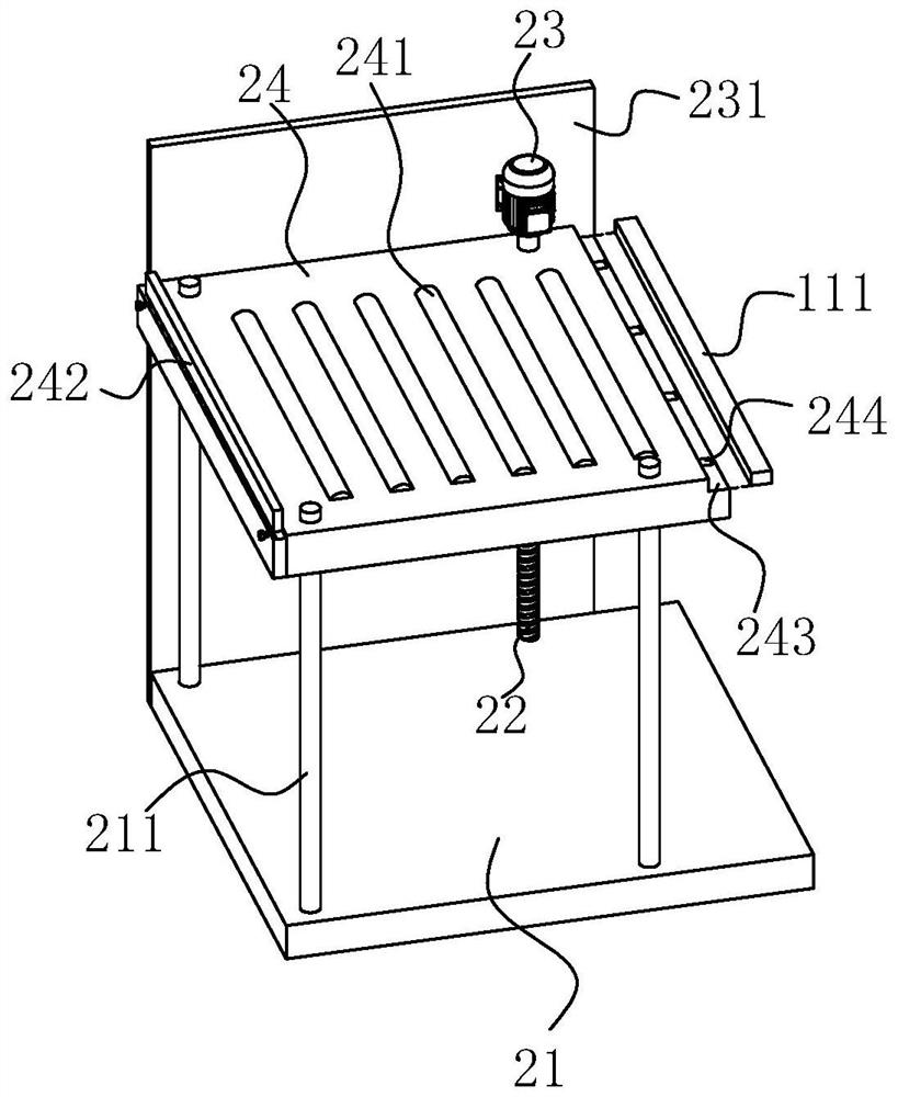
[0033] see figure 1 and figure 2 , The feeding device 2 includes a base 21, a threaded rod 22 arranged vertically and rotatably connected with the base 21, a motor 23 driving the threaded rod 22 to rotate, and a feeding plate 24 arranged parallel to the base 21 and threaded with the threaded rod 22.

[0034] Several guid...


PUM


Abstract

The invention discloses an injection molding machine, and relates to the technical field of injection molding equipment. According to the technical scheme, the injection molding machine is characterized by comprising a rack and an injection molding device arranged at the top end of the rack; a workbench for placing a mold is arranged below the injection molding device; the injection molding machine further comprises a feeding device arranged on one side of the rack; and the feeding device comprises a base, a threaded rod which is vertically arranged and is rotationally connected with the base,a driving piece for driving the threaded rod to rotate, and a feeding plate which is parallel to the base and is in threaded connection with the threaded rod. The injection molding machine has the effect of conveniently conveying the mold onto the equipment workbench.

Description

technical field [0001] The present application relates to the technical field of injection molding equipment, in particular to an injection molding machine. Background technique [0002] Injection molding machine, also known as injection molding machine or injection machine, is called beer machine in many factories, and injection molding products are called beer pieces. It is the main molding equipment for making thermoplastics or thermosetting materials into various shapes of plastic products with plastic molding molds. With the increase of patterns of plastic products, one injection molding machine with a set of specific molds can no longer meet the requirements of plastic product manufacturers. many. However, due to the heavy weight of medium-sized and slightly larger molds, it is laborious to carry them directly by hand, and it is inconvenient to replace the molds. Contents of the invention [0003] In view of the deficiencies in the prior art, the purpose of this a...

Claims


Application Information

Patent Timeline
IPC IPC(8): B29C45/17
CPCB29C45/1742B29C45/1756
Inventor 宋野张文华文贤敏
Owner 上海莎安精密注塑有限公司
Why Eureka
Try Eureka