
A fully protected milling machine crane

A full-protection, milling machine technology, applied in the direction of load block, load hanging element, trolley crane, etc., can solve the problems of manual loading and unloading, inconvenient lifting, unadjustable force, etc., to achieve the effect of improving work efficiency

Active Publication Date: 2022-07-19
安徽新诺精工股份有限公司
View PDF0 Cites 0 Cited by
  • Summary
  • Abstract
  • Description
  • Claims
  • Application Information

AI Technical Summary

Problems solved by technology

[0002] At present, in existing machining factories, the loading and unloading of workpieces is generally done manually or by driving. For heavy workpieces, manual loading and unloading is more difficult, and generally requires driving to operate. If there is no driving in the workshop, it will be very inconvenient
[0003] Generally, in the case of using a crane, it only plays a lifting role, and the position of the hoisted pulley assembly cannot be adjusted, resulting in inconvenient lifting and unable to adjust the force. For this reason, we propose a full protection Milling machine crane

Method used


Image

  • A fully protected milling machine crane
  • A fully protected milling machine crane
  • A fully protected milling machine crane

Examples


Embodiment Construction

[0035] The technical solutions of the present invention will be clearly and completely described below with reference to the embodiments. Obviously, the described embodiments are only a part of the embodiments of the present invention, rather than all the embodiments. Based on the embodiments of the present invention, all other embodiments obtained by those of ordinary skill in the art without creative efforts shall fall within the protection scope of the present invention.

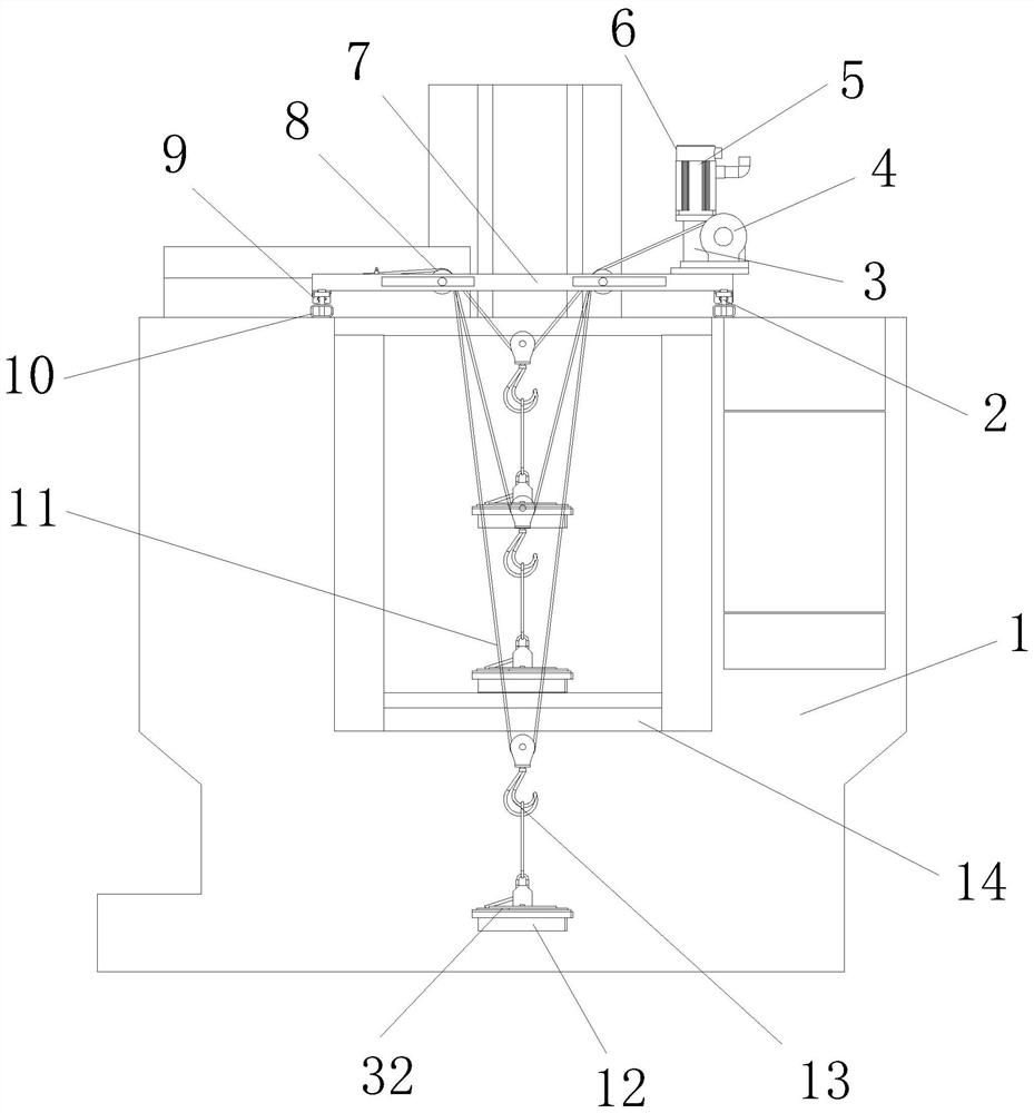
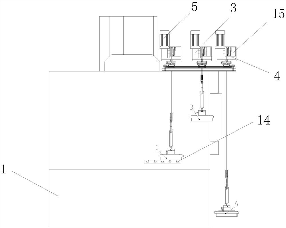
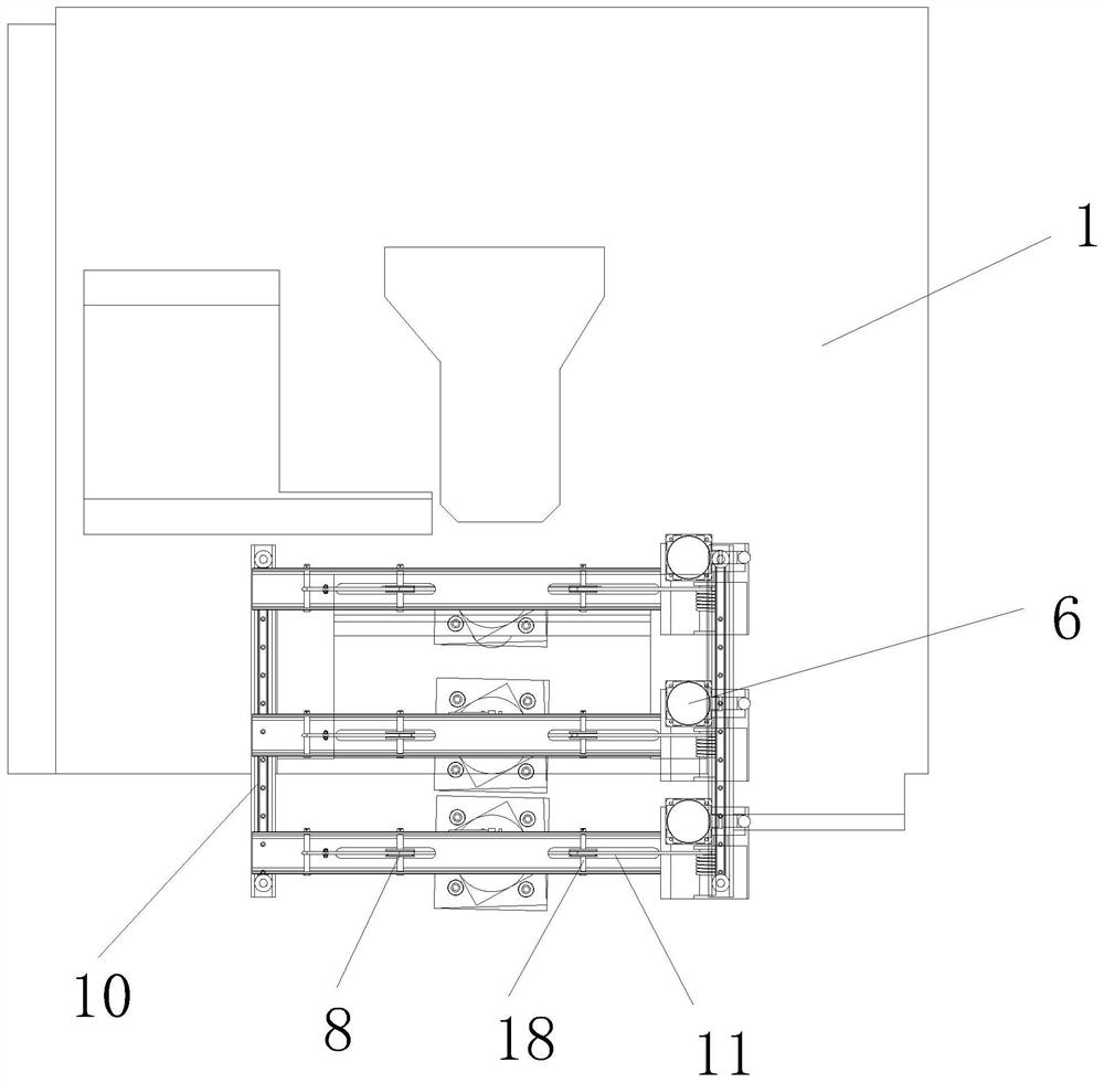
[0036] see Figure 1-6 As shown, a fully protected milling machine crane includes a mounting shell 1, a reducer 3, a beam 7, a guide wheel 8, a wire rope 11, a hook 13, a connecting rod 18, an adjustment spring 20, an adjustment rod 25 and a limit rod 28 , the top of the installation housing 1 is provided with a beam 7, and the top of the beam 7 is installed with an electric rope winding machine 6;

[0037] Limiting grooves 23 are symmetrically formed at the top of the beam 7, and guiding grooves are sym...


PUM


Abstract

The invention discloses a full-protection milling machine crane, which comprises an installation casing, a reducer, a beam, a guide wheel, a wire rope, a hook, a connecting rod, an adjustment spring, an adjustment rod and a limit rod. The top of the installation casing is provided with a A beam, an electric rope winding machine is installed on the top of the beam; a limit slot is symmetrically arranged on the top of the beam, and guide grooves are symmetrically opened on both sides of the limit slot, and a connecting rod is arranged in the limit slot, and is connected to the The rod is slidably connected in the limit groove, the two ends of the connecting rod respectively penetrate the corresponding side walls of the beam, and the connecting rod is slidably connected with the guide groove, a guide wheel is arranged in the limit groove, and the guide wheel is sleeved On the outside of the connecting rod, the present invention releases the limit of the limiting rod and the fixing groove through the mutual cooperation of the pull ring, the adjusting rod, the limit rod, the torsion spring, the fixed groove, the connecting rod and the adjusting spring, so that the guide The position of the wheel can be adjusted, the size of the force can be adjusted, and the work efficiency can be improved.

Description

technical field [0001] The invention relates to a milling machine crane, in particular to a full-protection milling machine crane, and belongs to the technical field of processing machine tools. Background technique [0002] At present, in existing machining factories, the loading and unloading of workpieces is generally performed manually or by driving. For heavier workpieces, manual loading and unloading is more laborious, and generally requires driving to operate. If there is no driving in the workshop, it will be very inconvenient. [0003] Generally, in the case of using a crane, it only plays a hoisting role, and the position of the hoisted pulley assembly cannot be adjusted, resulting in inconvenient hoisting and inability to adjust the force. For this reason, we propose a full protection Milling machine crane. SUMMARY OF THE INVENTION [0004] The purpose of the present invention is to provide a fully protected milling machine crane. By pulling the pull ring, the ...

Claims


Application Information

Patent Timeline
Patent Type & Authority Patents(China)
IPC IPC(8): B66C19/00B66C11/02B66C11/16B66C9/14B66C13/08
CPCB66C19/00B66C11/02B66C11/16B66C9/14B66C13/08
Inventor 刘伟李琴谢振涛张立新
Owner 安徽新诺精工股份有限公司
Learn More