a pullout pile

The invention relates to a technology of anti-uplift piles and pile heads, which is applied to anti-uplift piles. It can solve the problems of loss of pull-out resistance, low buoyancy of structural strength, and influence on the pressure-bearing performance of piles, so as to improve pull-out resistance, reduce difficulty, and ensure compressive performance.

Active Publication Date: 2021-10-26
THE THIRD CONSTR OF CHINA CONSTR EIGHTH ENG BUREAU
View PDF8 Cites 2 Cited by
  • Summary
  • Abstract
  • Description
  • Claims
  • Application Information

AI Technical Summary

Problems solved by technology

However, the enlarged head of the uplift pile of this patent is only formed by the opened sleeve plate, and its structural strength and the buoyancy that it can bear are all extremely low; The lower part of the plate leaves unfilled coating gaps, so that the pile body is in a suspended state, which will greatly affect the pressure bearing performance of the pile body, and the opening of the sleeve plate depends entirely on the core rod to provide the slide. block strength, which requires that the core rod must provide a constant pulling force for the slider during the entire life of the pile, otherwise, the stretched casing is very easy to be under the pressure of the upper coating or when the pile floats up. Closed again, thus completely losing the pull-out function

Method used


Image

  • a pullout pile
  • a pullout pile
  • a pullout pile

Examples


Embodiment 1

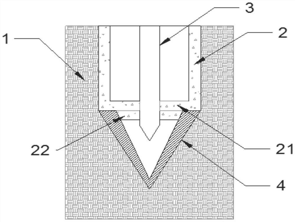
[0042] Such as figure 1 As shown, the uplift pile according to the present invention includes a prefabricated pile body 2. The pile body 2 in this embodiment is preferably a cylindrical structure. 21 coaxial boss 22; the upper surface of the bottom plate 21 and the lower surface of the boss 22 are provided with mounting holes that penetrate the bottom plate 21 and the boss 22 at corresponding positions, and a one-way grouting pipe 3 is inserted in the mounting hole, and the one-way grouting The outer wall of the pipe 3 is sealed with the inner wall of the installation hole; the position where the one-way grouting pipe 3 contacts the upper surface of the bottom plate 21, and the position where the one-way grouting pipe 3 contacts the lower surface of the boss 22 are all equipped with a clamping structure to ensure The one-way grouting pipe 3 remains stable during the high-pressure grouting process and will not be detached from the installation hole. The clamping structure in th...

Embodiment 2

[0048] In this embodiment, on the basis of Embodiment 1, the anti-extraction pile head 4 has been improved as follows:

[0049] Such as Figure 6 , 7 As shown, the outer wall of each sub-shell 41 is vertically provided with a side plate 46, the side plate 46 is perpendicular to the outer wall of the sub-shell 41, and the side plate 46 is a triangular plate including a bottom 461, a side 462, and a hypotenuse; the bottom of the side plate 46 One end of the edge 461 away from the cone point of the pile head 4 is not higher than the other end of the bottom edge 461 of the side plate 46, and is not higher than the cone point of the pile head 4. The other end of the bottom edge 461 and the cone point of the pile head 4 are all equal in height; the side plate 46 can provide support for the spliced ​​pile head 4, so that it can be stably placed vertically on the ground at the piling point without causing the shell The self-weight of 41 is scattered, thereby ensuring convenient dock...

Embodiment 3

[0051] In this embodiment, on the basis of Embodiment 1, the anti-extraction pile head 4 has been improved as follows:

[0052] Such as Figure 9 , 10 As shown, the top of the sub-shell 41 is a fan-shaped plate 47 structure, and the two ends of the fan-shaped plate 47 near the two sides of the sub-shell 41 are respectively provided with a lower half plate 471 and an upper half plate 472, and the lower half plate 471 and the upper half plate 472. The thickness is half of the thickness of the other parts of the fan-shaped plate 47. At the same time, the upper end of the conical wall of the sub-shell 41 corresponding to the upper half-plate 472 is provided with a notch 411 for installing the lower half-plate 471 to ensure that the lower part of the two adjacent sub-shells 41 The half plate 471 and the upper half plate 472 can be clamped together, and the four sub-shells 41 can be spliced ​​together to form a complete pile head 4 with an annular roof structure. Such as Figure ...


PUM


Abstract

The invention provides an uplift-resistant pile, belonging to the technical field of pile foundation engineering, comprising a pile body and a pile head, and the pile head is movably arranged at the lower part of the pile body. There is a base plate at the bottom of the pile body, and a boss matching the pile head is provided on the lower surface of the base plate. The one-way grouting pipe runs through the base plate and the boss. The sub-shells are spliced, the diameter of the bottom is not larger than the diameter of the pile body, avoiding the gap between the pile body and the soil layer, ensuring the verticality of the pile body and the friction between the pile body surface and the soil layer; injecting high-pressure concrete into the pile head When grouting, the sub-shell expands, forming an expanding head at the bottom of the pile body, and the continuous high-pressure concrete slurry overflows and combines with the soil layer to form a cement stone body, which can prevent underground mud from mixing into the expanding head, thereby ensuring the structural strength of the expanding head The pores formed during the opening of the pile head are filled in time by the injected concrete slurry, and no pores will be formed at the bottom of the pile body, effectively ensuring the compressive performance of the pile body.

Description

technical field [0001] The invention belongs to the technical field of pile foundation engineering, in particular to an uplift-resistant pile. Background technique [0002] Pull-out piles are widely used in anti-floating of large basements, pull-out resistance of high-rise buildings, pull-out resistance of offshore dock platforms, anchor pile foundations of suspension bridges and cable-stayed bridges, pile foundations of large dock floors, and anchor pile foundations in static load test piles and other fields. When a part of the underground structure of the construction project is lower than the water level of the surrounding soil, uplift piles need to be installed to offset the buoyancy force generated by the water in the soil on the underground structure of the construction project, so as to ensure the stability of the construction project. [0003] Existing anti-uplift piles are mainly manufactured by cast-in-place method, and the technological process mainly includes: d...

Claims


Application Information

Patent Timeline
Patent Type & Authority Patents(China)
IPC IPC(8): E02D5/52E02D5/44E02D5/30
CPCE02D5/30E02D5/44E02D5/52E02D5/523E02D5/526
Inventor 彭影星徐旭马怀章管磊王峰顺梅江涛
Owner THE THIRD CONSTR OF CHINA CONSTR EIGHTH ENG BUREAU
Why Eureka
Try Eureka