Sealing structure of valve and electric control throttle valve with same

A technology of sealing structure and sealing ring, applied in valve details, valve operation/release device, valve lift, etc., can solve the problems of poor sealing effect, sealing failure, large change of compression force with size, etc., and achieve elastic modulus The effect of small change, guaranteed reliability, and small fluctuation of force value

Pending Publication Date: 2021-01-15
ZHEJIANG KEBODA IND
View PDF0 Cites 0 Cited by
  • Summary
  • Abstract
  • Description
  • Claims
  • Application Information

AI Technical Summary

Problems solved by technology

Since the sealing ring will harden at high and low temperatures, and the compression force varies greatly with the size, the sealing effect will deteriorate under high and low temperature conditions
In addition, the existing electronically controlled throttle valve has no assembly direction adjustment structure. In the case of large cumulative deviations in assembly and parts, the central axis of the sealing ring and the central axis of the through hole of the valve core will not be on a straight line. , leading to seal failure

Method used


Image

  • Sealing structure of valve and electric control throttle valve with same
  • Sealing structure of valve and electric control throttle valve with same
  • Sealing structure of valve and electric control throttle valve with same

Examples


Embodiment Construction

[0023] The present invention will be described in detail below in conjunction with the accompanying drawings and specific embodiments.

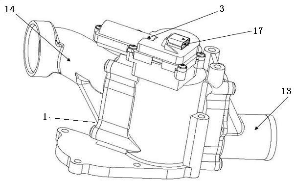
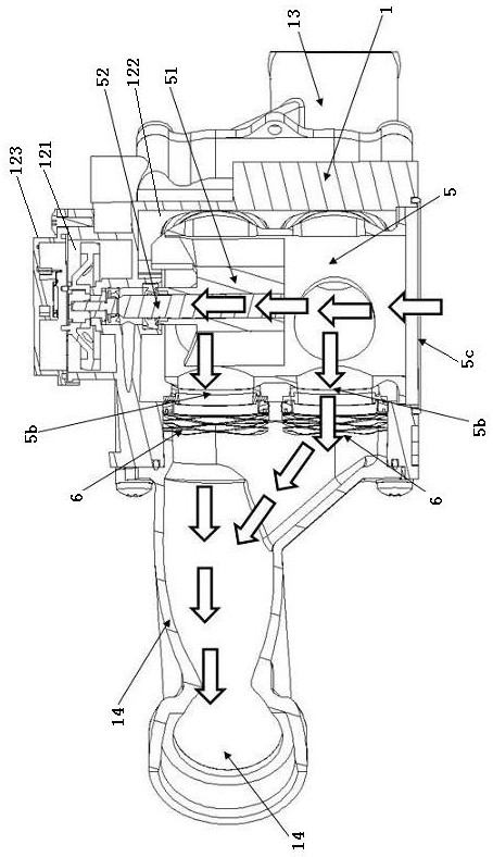
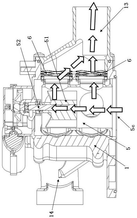
[0024] see Figure 1 to Figure 8 . An electronically controlled throttle valve according to an embodiment of the present invention includes a valve body 1 , a control transmission mechanism 2 , a motor 3 , a spool position sensor 4 and a spool 5 .

[0025] The valve body 1 includes a valve body body 12 , a large circulation joint 13 and a small circulation joint 14 . The large circulation joint 13 and the small circulation joint 14 are respectively connected to the side of the valve body body 12 . The valve body 12 is provided with an electrical cavity 121 and a fluid cavity 122. The electrical cavity 121 is used to accommodate the control transmission mechanism 2 and the motor 3. The fluid cavity 122 is used to transport fluid. The electrical cavity 121 and the fluid cavity 122 are separated from each other by a partition . In this embod...


PUM


Abstract

A sealing structure of a valve comprises a valve body, a valve element, a sealing ring, an installation support, an elastic ring, a wave spring and a pressure applying part. The valve element is rotationally arranged on the valve body. The sealing ring is installed on the installation support, and the installation support is provided with a fluid through hole in the axial direction. The elastic ring is arranged between the installation support and the wave spring, the front end surface of the elastic ring is in sealed contact with the rear end of the installation support, and the outer peripheral surface of the elastic ring is in sealed contact with the inner surface of the valve body. The wave spring is in a corrugated pipe shape, and the front end of the wave spring abuts against the rear end of the elastic ring. The pressure applying part abuts against the rear end of the wave spring so as to apply axial pressure to the wave spring, and the axial pressure is transmitted to the sealing ring through the elastic ring and the installation support so that the sealing ring can be tightly attached to the surface of the valve element. A good sealing effect can also be maintained in a high-low temperature environment and under the condition that assembly and part size accumulative deviation exists.

Description

technical field [0001] The present invention relates to valve technology. Background technique [0002] In order to reduce specific fuel consumption (CO 2 emission), shorten the engine warm-up time, and improve the reliability of the engine, it is necessary to use an electronically controlled throttle valve for thermal management of the engine. The electronically controlled throttle valve is usually installed on the engine block, which adopts a mechanical and electrical integration design, and the system is compact and highly integrated. It precisely controls the rotation angle of the low-resistance ball valve through the high-efficiency actuator driven by the DC motor and the high-precision inductive position sensor, so as to realize the on-demand control of the flow in each branch of the cooling system. Through precise temperature control, the electronically controlled throttle valve can improve the working efficiency of the engine and other components, thereby minimizin...

Claims


Application Information

Patent Timeline
Patent Type & Authority Applications(China)
IPC IPC(8): F16K1/00F16K1/32F16K1/36F16K1/48F16K31/04F16K31/53F16K37/00F16F1/18
CPCF16F1/185F16K1/00F16K1/32F16K1/36F16K1/48F16K31/046F16K31/53F16K37/0041
Inventor 杨振亚巴文辉周宇雯
Owner ZHEJIANG KEBODA IND
Why Eureka
Try Eureka