Reheating regulating valve of subcritical 300 MW steam turbine

A reheat regulating valve and steam turbine technology, which is applied in the field of steam turbines, can solve the problems of poor tightness and poor regulation, and achieve the effects of ensuring effective operation, improving tightness and regulation, and improving work efficiency

Pending Publication Date: 2021-01-15
国能(泉州)热电有限公司 +1
View PDF0 Cites 1 Cited by
  • Summary
  • Abstract
  • Description
  • Claims
  • Application Information

AI Technical Summary

Problems solved by technology

[0003] In order to solve the common problems of poor tightness and poor regulation of the existing subcritical 300MW turbin

Method used


Image

  • Reheating regulating valve of subcritical 300 MW steam turbine

Examples


specific Embodiment approach 1

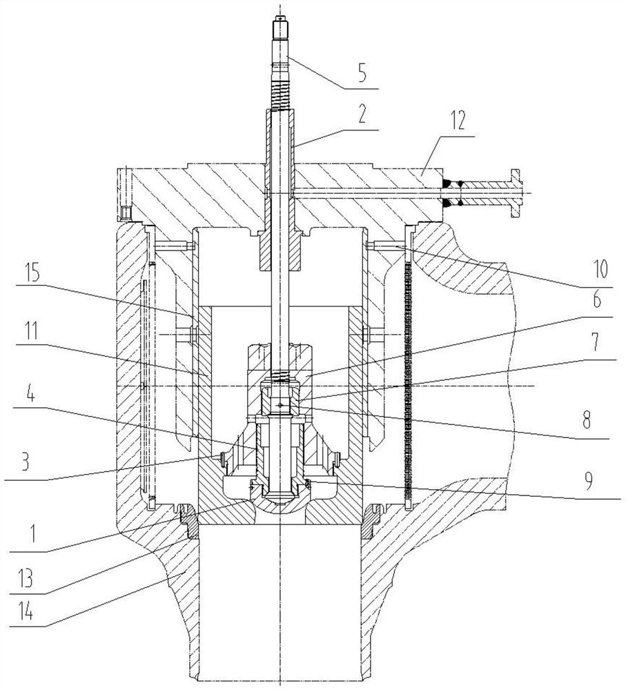
[0008] Specific implementation mode one: combine figure 1 Explain that a subcritical 300MW steam turbine reheat regulating valve described in this embodiment includes a pre-opening valve 1, a lock nut 4, a valve stem 5, a medium pressure regulating valve connecting sleeve 6, a valve disc 11, a valve cover 12, a valve Seat 13, valve body 14 and bushing 15, valve stem 5 are inserted vertically on the end face of valve cover 12, the lower end of valve stem 5 is fixedly connected with pre-opening valve 1, and the upper end of pre-opening valve 1 is fixedly connected with locking valve. The nut 4, the upper end of the lock nut 4 is provided with a connecting nut 7, the lock nut 4 and the connecting nut 7 are all arranged on the outside of the lower end of the valve stem 5, and the upper end of the pre-opening valve 1 is provided with a medium pressure regulating valve connecting sleeve 6, The upper end of the connecting sleeve 6 of the medium pressure regulating valve is set on the...

specific Embodiment approach 2

[0010] Specific implementation mode two: combination figure 1 Explanation, in this embodiment, the outer peripheral side wall of the lower end of the connecting sleeve 6 of the medium pressure regulating valve described in this embodiment extends outwards with an extension section, and the outer peripheral side wall of the extension section is fixedly connected to the inner side wall of the valve disc 11 . Other compositions and connection methods are the same as those in Embodiment 1.

specific Embodiment approach 3

[0011] Specific implementation mode three: combination figure 1 It should be noted that a plurality of connecting sleeve through holes are evenly distributed along the circumferential direction on the extension section of this embodiment. Other compositions and connection methods are the same as those in the second embodiment.


PUM


Abstract

The invention discloses a reheating regulating valve of a subcritical 300 MW steam turbine and relates to the technical field of steam turbines. The reheating regulating valve aims at solving the problems that an existing reheating regulating valve of a subcritical 300 MW steam turbine is commonly poor in tightness and poor in adjusting performance. The reheating regulating valve comprises a pre-opening valve, a locking nut, a valve rod, a medium-pressure regulating valve connecting sleeve, a valve disc, a valve deck, a valve seat, a valve body and a lining, the pre-opening valve is fixedly connected to the lower end of the valve rod, the locking nut is fixedly connected to the upper end of the pre-opening valve, a connecting nut is arranged at the upper end of the locking nut, and the medium-pressure regulating valve connecting sleeve is arranged at the upper end of the pre-opening valve. The medium-pressure regulating valve connecting sleeve is inserted into the valve disc, a valve disc through hole is formed in the middle of the lower end face of the valve disc, the pre-opening valve is arranged at the inner side end of the valve disc through hole, a circular ring sleeve is arranged at the lower end of the valve deck and arranged in the valve body, the steam inlet end of the valve body is arranged on one side of the circular ring sleeve, and the lining is arranged on the inner circumferential side wall of the circular ring sleeve. The upper end of the valve disc is inserted into the lining. The reheating regulating valve is used for the 300 MW steam turbine.

Description

technical field [0001] The invention relates to the technical field of steam turbines, in particular to a subcritical 300MW steam turbine reheat regulating valve. Background technique [0002] With the increasing development of my country's industry and agriculture, the power industry's requirements for the steam turbine manufacturing industry continue to increase, and steam turbines are developing towards large capacity, high parameters, low pollution, high reliability, high load adaptability, high degree of automation, safety, and economy. Modern large-scale steam turbines generally adopt a structure with multiple stages, multiple cylinders, and multiple exhausts; the cylinders adopt a structure of inner and outer double or multi-layer cylinders. The steam turbine design must choose a reasonable thermodynamic cycle, the flow part of the steam turbine should have good thermal and aerodynamic characteristics, the main and auxiliary machines of the steam turbine and their mai...

Claims


Application Information

Patent Timeline
IPC IPC(8): F16K1/02F16K1/32F16K1/44F16K1/48F16K27/02F01D17/10
CPCF01D17/10F16K1/02F16K1/32F16K1/443F16K1/487F16K27/02
Inventor 张志业涂朝阳林宝森娄殿阁刁美玲李志炜
Owner 国能(泉州)热电有限公司
Why Eureka
Try Eureka