Terminal positioning method and device, computer equipment and storage medium

A terminal positioning and terminal technology, applied in the field of satellite navigation, can solve the problems of affecting positioning, correcting deviation, and the accuracy can only be in the order of 10m, so as to achieve the effect of improving positioning accuracy.

Pending Publication Date: 2021-01-15
GUANGZHOU HI TARGET SURVEYING INSTRUMENT CO LTD
View PDF7 Cites 9 Cited by
  • Summary
  • Abstract
  • Description
  • Claims
  • Application Information

AI Technical Summary

Problems solved by technology

[0002] The early GNSS positioning technology is a pseudo-range single-point positioning based on pseudo-range observations. However, due to various errors, the accuracy can only be on the order of 10m
In order to improve the accuracy, differential technology has emerged. At present, real-time dynamic carrier phase differential technology is widely used. The accuracy can reach centimeter level, but the working distance is limited. In view of this, network RTK technology came into being.
[0003] VRS (Virtual Reference Station, Virtual Reference Station) technology is the most mature and widely used network RTK technology at present. VRS technology is a technology for positioning by building a triangular network through multiple reference stations. The main technology of network RTK is to use it in the triangular network The linear interpolation model interpolates the relevant parameters here to provide RTK services. However, some or all of the reference stations in the triangulation network constructed from this only support the GPS / GLONASS dual system, which makes other satellite systems such as BDS / GALIEO unusable. , it cannot provide accurate positioning when the baseline is long, and when the user is not in the triangulation network, the atmospheric error correction value interpolated by the linear interpolation model will deviate, thus affecting the positioning
[0004] Therefore, the current positioning method has the defect of low positioning accuracy.

Method used


Image

  • Terminal positioning method and device, computer equipment and storage medium
  • Terminal positioning method and device, computer equipment and storage medium
  • Terminal positioning method and device, computer equipment and storage medium

Examples


Embodiment Construction

[0052] In order to make the purpose, technical solution and advantages of the present application clearer, the present application will be further described in detail below in conjunction with the accompanying drawings and embodiments. It should be understood that the specific embodiments described here are only used to explain the present application, and are not intended to limit the present application.

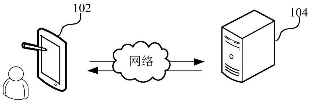
[0053] The terminal positioning method provided by this application can be applied to such as figure 1 shown in the application environment. Wherein, the terminal 102 communicates with the server 104 through the network. The terminal 102 can send a positioning request to the server 104, and the server 104 can respond to the positioning request, and obtain the approximate coordinates of the terminal 102 in the observation area formed by multiple reference stations, and determine the virtual reference station corresponding to the approximate coordinates. The server 104 can ...


PUM


Abstract

The invention relates to a terminal positioning method and device, computer equipment and a storage medium. The method comprises the following steps: obtaining general coordinates of a terminal in anobservation area formed by a plurality of reference stations, determining virtual reference stations corresponding to the general coordinates, obtaining delay influence factors corresponding to the observation area according to the positions of the reference stations and the atmospheric delay characteristics of the reference stations, and obtaining the delay influence factors corresponding to theobservation area; according to the positions of the virtual reference stations and the delay influence factors, acquiring an atmospheric delay characteristic of the virtual reference station, determining a virtual observation value corresponding to the virtual reference station according to the atmospheric delay characteristic of the virtual reference station, and sending the virtual observation value to the terminal, so the terminal performs positioning according to the virtual observation value. Compared with a conventional positioning method of forming a triangulation network based on a plurality of reference stations, the scheme utilizes the atmospheric delay characteristics and delay influence factors of the virtual reference stations to obtain the virtual observation value for positioning the terminal, and the effect of improving the positioning precision is achieved.

Description

technical field [0001] The present application relates to the technical field of satellite navigation, in particular to a terminal positioning method, device, computer equipment and storage medium. Background technique [0002] The early GNSS positioning technology is a pseudo-range single-point positioning based on pseudo-range observations. However, due to various errors, the accuracy can only be on the order of 10m. In order to improve the accuracy, differential technology has emerged. At present, real-time dynamic carrier phase differential technology is widely used. The accuracy can reach centimeter level, but the working distance is limited. In view of this, network RTK technology came into being. [0003] VRS (Virtual Reference Station, Virtual Reference Station) technology is the most mature and widely used network RTK technology at present. VRS technology is a technology for positioning by building a triangular network through multiple reference stations. The main t...

Claims


Application Information

Patent Timeline
Patent Type & Authority Applications(China)
IPC IPC(8): G01S19/39G01S19/44G01S19/07G01S19/11
CPCG01S19/396G01S19/44G01S19/072G01S19/073G01S19/11
Inventor 杨克凡张晋升汤逸豪左翔曾伟李成钢
Owner GUANGZHOU HI TARGET SURVEYING INSTRUMENT CO LTD
Why Eureka
Try Eureka