Supercharge Your Innovation With Domain-Expert AI Agents!

Tape feeder

A belt feeder and feeder technology, applied in the direction of electrical components, electrical components, etc., can solve the problems of unable to maintain the carrier tape, the carrier tape is easy to bend, etc., achieve relaxation accuracy, realize part cost, and realize positioning accuracy Effect

Active Publication Date: 2021-01-15
FUJI KK
View PDF14 Cites 2 Cited by
  • Summary
  • Abstract
  • Description
  • Claims
  • Application Information

AI Technical Summary

Problems solved by technology

Carrier tape, on the other hand, tends to flex
That is, when the operator directly applies a propulsion force to the carrier tape, the load of the peeling knife cannot be maintained and the carrier tape cannot be maintained.

Method used


Image

  • Tape feeder
  • Tape feeder
  • Tape feeder

Examples


Embodiment Construction

[0027] 1. Outline structure of component mounting machine 1

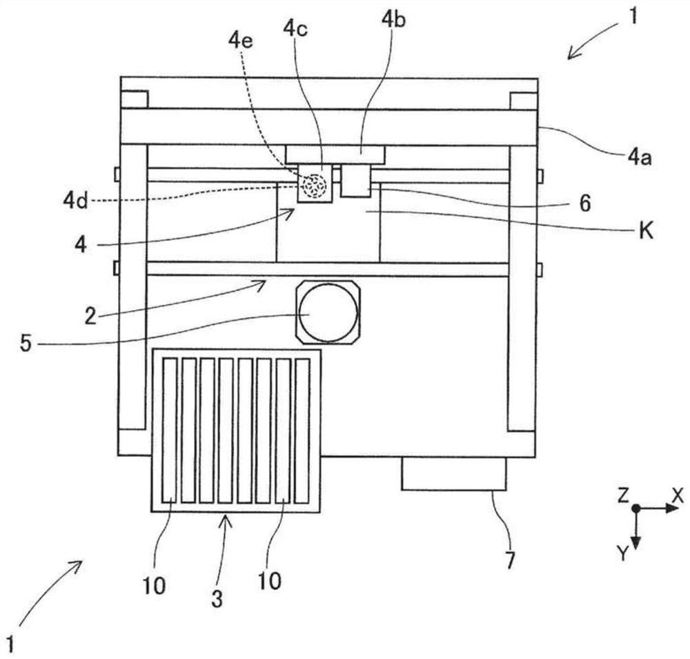
[0028] Hereinafter, an embodiment to which the tape feeder disclosed in this specification is applied will be described with reference to the drawings. First, refer to figure 1 , the schematic configuration of the component mounting machine 1 using the tape feeder 10 will be described. In addition, in figure 1 In the horizontal width direction of the component mounting machine 1 ( figure 1 left and right direction) as the X direction, the horizontal length direction of the component mounting machine 1 ( figure 1 Up and down direction) is set as the Y direction, and the vertical direction perpendicular to the X direction and the Y direction ( figure 1 The direction vertical to the paper surface) is set as the Z direction.

[0029] Such as figure 1 As shown, the component mounting machine 1 mainly includes a substrate conveying device 2 , a component supply device 3 , a component transfer device 4 , a component ...


PUM


Abstract

This tape feeder is provided with: a drive sprocket which is driven by a motor and which pitch-feeds a carrier tape to convey an electronic component to a prescribed component supply position; a release blade which, in the carrier tape conveyance direction, is provided upstream from the position where the drive sprocket and feed holes mesh, and which releases at least part of the area where a cover tape and a base tape are bonded together; a first tape holding part which holds the carrier tape at the position where the release blade releases the cover tape, the component supply position, and the position where the drive sprocket and feed holes mesh; a manual sprocket which is provided in a position at which the carrier tape conveyance distance from the feed hole meshing position to the release blade is longer than the carrier tape conveyance distance from the release blade to the component supply position, and which can be operated manually and can convey the carrier tape, drawn out from a reel, to the first tape holding part; and a second tape holding part which holds the carrier tape above the manual sprocket.

Description

technical field [0001] The invention relates to a belt feeder. Background technique [0002] A carrier tape is known that includes a base tape in which electronic components are accommodated, and a cover tape that prevents the electronic components from falling off by being bonded to the base tape. When conveying the electronic components accommodated in this carrier tape to a component supply position by a tape feeder, it is necessary for a tape feeder to peel off a cover tape from a base tape. Therefore, in the tape feeder, a peeling knife for peeling the cover tape from the base tape is provided on the upstream side in the conveyance direction of the carrier tape from the component supply position. [0003] Here, a drive sprocket for pitch-feeding the carrier tape is provided in the tape feeder. Furthermore, when the operator newly installs the reel on which the carrier tape is wound, it is necessary to pull the carrier tape from the reel and transport it to a position ...

Claims


Application Information

Patent Timeline
Patent Type & Authority Applications(China)
IPC IPC(8): H05K13/02
CPCH05K13/0419
Inventor 田中启太细井规生
Owner FUJI KK
Features
  • R&D
  • Intellectual Property
  • Life Sciences
  • Materials
  • Tech Scout
  • Unparalleled Data Quality
  • Higher Quality Content
  • 60% Fewer Hallucinations
Learn More