A construction engineering bar material cutting device

A construction engineering and cutting device technology, applied in positioning devices, manufacturing tools, metal processing equipment, etc., can solve problems such as affecting bar cutting, inconvenient use, inconvenient cleaning operations, etc., to improve work efficiency, improve work efficiency, Use good effect

Active Publication Date: 2022-02-11
安徽雄康建设工程有限公司
View PDF6 Cites 0 Cited by
  • Summary
  • Abstract
  • Description
  • Claims
  • Application Information

AI Technical Summary

Problems solved by technology

[0002] Construction engineering refers to the engineering entity formed through the construction of various housing buildings and their ancillary facilities and the installation activities of the supporting lines, pipelines, and equipment. Bars are often used in construction projects, and some bars need to be used The cutting device cuts it to facilitate the use of the bar, but the existing bar cutting device is often not convenient for the clamping and fixing of the bar, and it takes more time to fix the bar before cutting, so that Not only is it not convenient to use, but it also affects the working efficiency of the device, and the fixation of the bar is not firm enough, which easily affects the cutting of the bar, and it takes a long time to stop and replace a batch of bars after cutting a batch of bars. , so that the efficiency of the device is not ideal, and the existing device cannot perform dust reduction treatment when cutting the bar. The dust generated during cutting is likely to pollute the surrounding environment, and it is not convenient for subsequent cleaning operations

Method used


Image

  • A construction engineering bar material cutting device
  • A construction engineering bar material cutting device
  • A construction engineering bar material cutting device

Examples


Embodiment 1

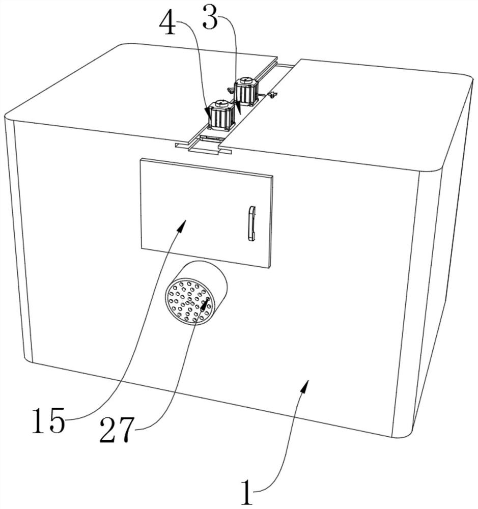
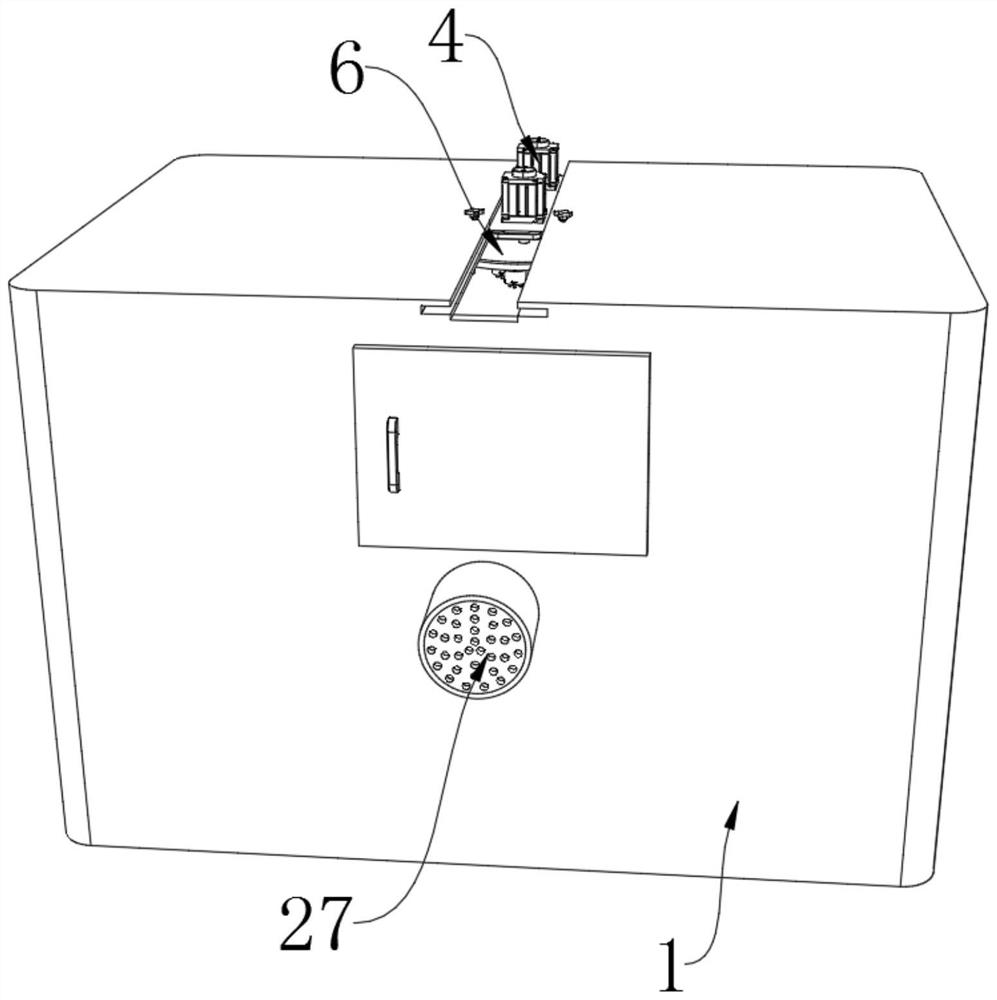
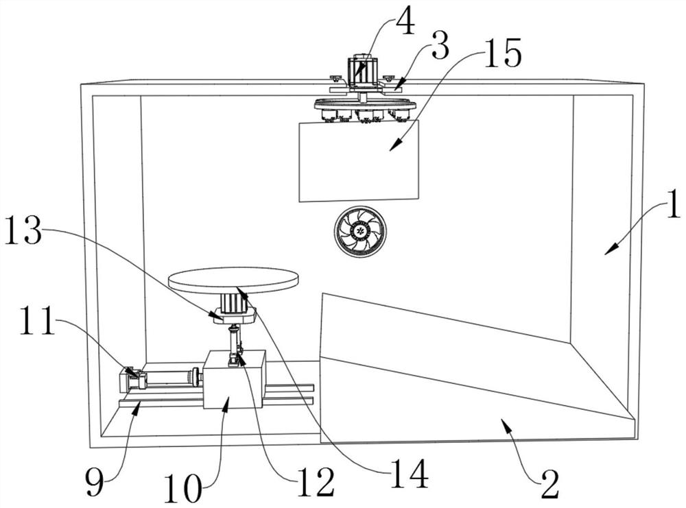
[0032] refer to Figure 1-8 , a construction engineering bar material cutting device, comprising a cutting box 1, one end of the inner bottom of the cutting box 1 is fixed with a material guide bottom plate 2, the top of the cutting box 1 is slidably connected with a movable support plate 3, and the movable support plate 3 Both sides are fixed with push-pull handles 8, both sides of the top of the movable support plate 3 are screw-fixed with a rotating motor 4, the output end of the rotating motor 4 runs through the movable support plate 3 and is fixed with a connecting shaft 5, and the bottom of the connecting shaft 5 is fixed There is a fixed disc 6, and the bottom of the fixed disc 6 is uniformly fixed with a plurality of clamping mechanisms 7, and both sides of the cutting box 1 are connected with a box door 15 by a hinge, and the side of the box door 15 away from the cutting box 1 is A door handle is welded, the top of the cutting box 1 and the top of the movable support ...


PUM


Abstract

The present invention relates to the technical field of construction devices, in particular to a construction engineering bar material cutting device, a construction engineering bar material cutting device, comprising a cutting box, one end of the inner bottom of the cutting box is fixed with a material guide bottom plate, and the cutting box body The top is slidably connected with a movable support plate, both sides of the movable support plate are fixed with push-pull handles, and both sides of the movable support plate top are screw-fixed with rotating motors. Through the structural design of the clamping mechanism, the present invention makes it more convenient for the device to fix the bar, improves the working efficiency of the device, and fixes the bar more firmly. Cooperate with the clamping mechanism, so that the device will not affect the cutting efficiency of the device when refueling, and thus greatly improve the working efficiency of the device. Through the structural design of the dust reduction processing mechanism, the device will The generated dust will not pollute the surrounding environment and is more environmentally friendly.

Description

technical field [0001] The invention relates to the technical field of construction devices, in particular to a construction engineering rod. Background technique [0002] Construction engineering refers to the engineering entity formed through the construction of various housing buildings and their ancillary facilities and the installation activities of the supporting lines, pipelines, and equipment. Bars are often used in construction projects, and some bars need to be used The cutting device cuts it to facilitate the use of the bar, but the existing bar cutting device is often not convenient for the clamping and fixing of the bar, and it takes more time to fix the bar before cutting, so that Not only is it not convenient to use, but it also affects the working efficiency of the device, and the fixation of the bar is not firm enough, which easily affects the cutting of the bar, and it takes a long time to stop and replace a batch of bars after cutting a batch of bars. , s...

Claims


Application Information

Patent Timeline
Patent Type & Authority Patents(China)
IPC IPC(8): B23D79/00B23Q3/00B23Q11/00
CPCB23D79/00B23Q3/00B23Q11/00
Inventor 罗仁富
Owner 安徽雄康建设工程有限公司
Why Eureka
Try Eureka