
Reverse limiting device for chain

A limit device and chain technology, applied in auxiliary devices, auxiliary welding equipment, welding/cutting auxiliary equipment, etc., can solve the problems of aggravated chain wear, increased movement resistance, and inconvenient installation, so as to reduce wear, simplify structure, and install convenient effect

Pending Publication Date: 2021-01-19
HENAN SENYUAN HEAVY IND
View PDF1 Cites 1 Cited by
  • Summary
  • Abstract
  • Description
  • Claims
  • Application Information

AI Technical Summary

Problems solved by technology

[0004] Although the above-mentioned device can realize the reverse limit of the chain, the blocks are located on the left and right sides of the chain, and there are three blocks arranged alternately on both sides. That is to say, the deflection of the chain in the left and right directions is completely limited by the blocks. This structure is not only complicated, but also the chain has to overcome the reaction force of the torsion springs of the three blocks when moving, which increases the movement resistance and also aggravates the movement. chain wear
In addition, when installing the chain, either the chain is cut off so that one end of the chain passes through the three blocks from bottom to top, or the three blocks need to be rotated to the limit position at the same time to provide space for the chain to be placed. Difficult to control, even one person can't complete it, which makes the installation very inconvenient

Method used


Image

  • Reverse limiting device for chain
  • Reverse limiting device for chain
  • Reverse limiting device for chain

Examples


Embodiment Construction

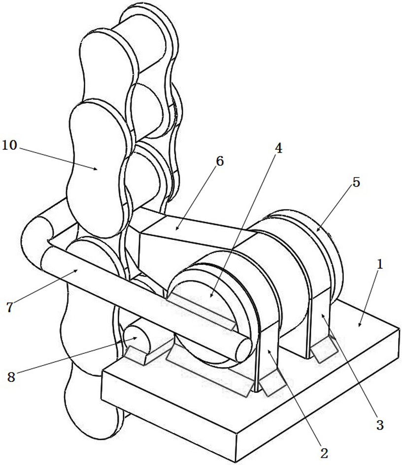
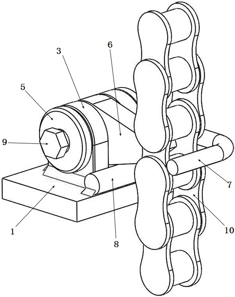
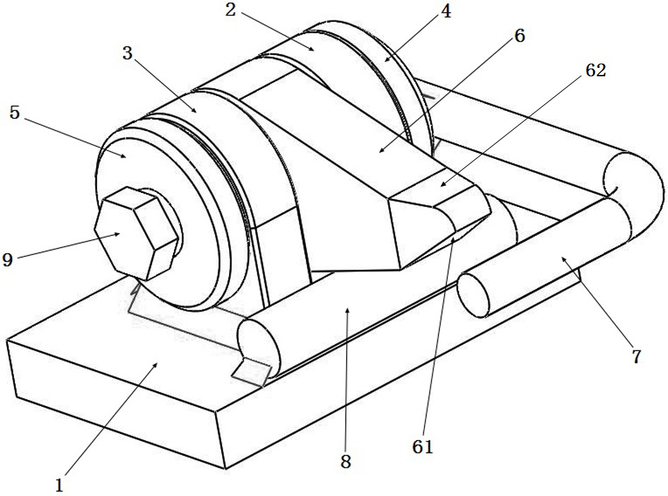
[0028] An embodiment of the chain reverse limiting device in the present invention is as Figure 1~Figure 6 As shown, it includes a base and a chain lock installed on the base that can be rotated at a certain rotation angle, wherein the base includes a base plate 1 used to be fixed on other equipment when in use and two parallel spaced sets that are welded and fixed on the base plate 1 The risers are respectively the left riser 2 and the right riser 3. Fixed shaft 4 is installed on left vertical board 2 and right vertical board 3, as Figure 6 As shown, the fixed shaft 4 is in the shape of a stepped shaft, the left end of which is a large end, and the right end is a small end. It is perforated, and its large end is matched with the side of the left vertical plate 2, and its small end is fixedly connected with the right vertical plate 3 by fasteners.

[0029] Specifically, a threaded hole is processed on the small end of the fixed shaft 4, and the end face of the small end is...


PUM


Abstract

The invention provides a reverse limiting device for a chain. The reverse limiting device comprises a base, wherein the base is provided with a chain locking part which is provided with a clamped endused for being clamped into a chain link gap; the clamped end is provided with a passing station which rotates to allow the chain to pass through when the chain moves forwards, and is further providedwith a locking station which is clamped into the chain link gap to lock the chain when the chain moves reversely; the base is further provided with a deviation preventing part, and the deviation preventing part comprises a stop surface opposite to the clamped end; and a chain walking space for the chain to pass through is formed between the stop surface and the clamped end, and a loading openingwhich communicates with the chain walking space and is used for loading the chain into the chain walking space is formed in one side of the stop surface and the clamped end. The reverse limiting device has the beneficial effects that reverse limiting of the chain is achieved; the structure is simplified through the one-to-one limiting mode of the clamped end and the stop surface; the chain does not need to overcome the counter-acting force of too many chain locking parts during moving, smooth moving of the chain is facilitated, chain wear is reduced; and meanwhile, the chain can be loaded intothe chain walking space from the loading opening in the side direction, so that installation is very convenient.

Description

technical field [0001] The invention relates to a chain reverse limiting device. Background technique [0002] The boom of the crane needs to be flipped and welded on the flip welding machine. The flip is realized by the movement of the chain. Due to the large mass of the boom of the crane, it is easy to cause inertial flipping during the flipping process, causing the chain to move up and down, resulting in chain wear. , and easily lead to a series of security issues. [0003] The Chinese utility model patent with the authorized announcement number CN207514169U discloses a rotating chain safety device (that is, a chain reverse limit device), which includes a mounting plate and a main body on the mounting plate. There is a side limiter, and the side limiter and the main body are connected by a connecting plate. The side limiter, the main body and the connecting plate form a chain running space for the chain to pass through. The chain running space is between the side limiter...

Claims


Application Information

Patent Timeline
IPC IPC(8): B23K37/047
CPCB23K37/047
Inventor 王凯陈文博杨晓锋张旭谢华华朱新民史重阳
Owner HENAN SENYUAN HEAVY IND
Learn More