Artificial stone edge trimmer
A technology of artificial stone and trimming machine, which is applied in the direction of stone processing tools, stone processing equipment, manufacturing tools, etc., can solve the problems of poor trimming effect, adverse effects on the health of workers, serious tool wear, etc., and achieve low risk , reduce the flying of dust, and ensure the health effect
- Summary
- Abstract
- Description
- Claims
- Application Information
AI Technical Summary
Problems solved by technology
Method used
Image

Examples
Embodiment 1
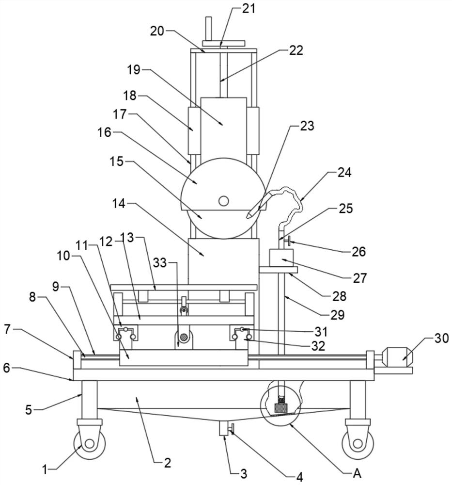
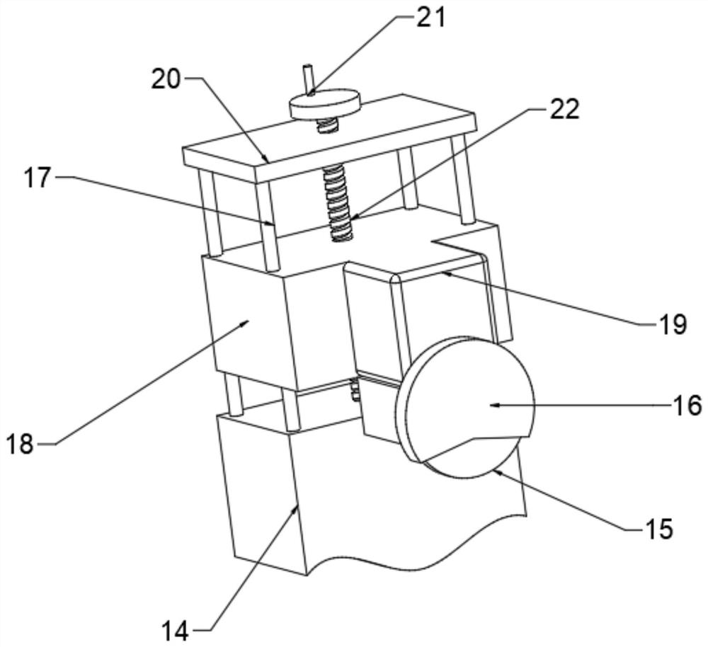
[0025] see Figure 1~3 , in an embodiment of the present invention, an artificial stone edge trimmer includes a cutter 15, a mounting plate 6, a sliding mechanism, a lifting mechanism, a spray mechanism and an angle adjustment mechanism, and the sliding mechanism includes a fixing seat 7, a first sliding rod 8, The slide table 10, the slide rail 32, the base 12 and the drive mechanism, the two ends of the top surface of the mounting plate 6 are symmetrically fixed and installed with a fixed seat 7, and the symmetrical fixed connection between the two fixed seats 7 is provided with two first slide bars 8 The slide table 10 is slidably connected to the two first slide rods 8, two slide rails 32 are symmetrically fixedly installed at both ends of the top surface of the slide table 10, and the two ends of the bottom surface of the base 12 are symmetrically fixedly installed with mounting blocks 11 and The middle position is fixedly connected with a connection seat 34, a slide groo...
Embodiment 2
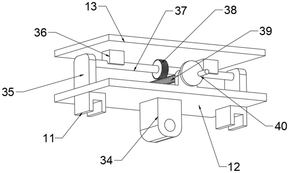
[0032] see figure 1 and 3 On the basis of Embodiment 1, the angle adjustment mechanism includes a placement plate 13, a second mounting seat 35, a rotating shaft 37, a worm gear 38 and a worm 39, and the two ends of the top surface of the base 12 are symmetrically fixedly installed with the second mounting seat 35, Rotating shaft 37 is installed between the two second mounting bases 35 and fixedly installed with turbine 38 in the middle of the periphery. Both sides of the middle position of the top surface of base 12 are symmetrically fixed with bearing seats, and worm 39 is installed in rotation. One end of the worm 39 rotates through the bearing seat and is fixedly installed with a first handwheel 40. The periphery of the rotating shaft 37 is symmetrically fixedly connected with the turbine 38. Two connecting blocks 36 are arranged. One end of each connection block 36 away from the rotating shaft 37 is fixedly connected with a placement plate 13 .
[0033] The working prin...
Embodiment 3
[0035] see figure 1 , on the basis of Embodiments 1 and 2, the spray mechanism includes a spray nozzle 23, a water pump 27 and a water tank 2, and the side of the support plate 14 is fixedly connected with an extending plate 28, and the top surface of the extending plate 28 is fixedly installed with a water pump. 27. The outlet end and the water inlet end of the water pump 27 are respectively connected with a first conduit 25 and a second conduit 29, the first conduit 25 is installed with a second valve 26, and the water tank 2 is fixedly connected to the bottom surface of the mounting plate 6, The water tank 2 is fixedly installed with a filter box 41, the end of the second valve 26 away from the water pump 27 is connected to the filter box 41 and fixedly installed with a filter screen 42 and a cleaning mechanism, the nozzle 23 is fixedly installed on the protective shell 16 and Pointing to the lowest point of the cutter 15 , a telescopic hose 24 is connected between the wate...
PUM
 Abstract
Description
Claims
Application Information
 - R&D Engineer
- R&D Manager
- IP Professional
- Industry Leading Data Capabilities
- Powerful AI technology
- Patent DNA Extraction
Browse by: Latest US Patents, China's latest patents, Technical Efficacy Thesaurus, Application Domain, Technology Topic.
© 2024 PatSnap. All rights reserved.Legal|Privacy policy|Modern Slavery Act Transparency Statement|Sitemap