
Injection molding excess material removing device

A technology of residual material and material column, which is applied in the field of injection molding equipment to remove residual material, can solve the problems of reducing production efficiency, low safety of manual cutting of residual material, and taking a long time, so as to prevent injury, increase safety, and improve The effect of work efficiency

Pending Publication Date: 2021-01-19
唐斌
View PDF4 Cites 0 Cited by
  • Summary
  • Abstract
  • Description
  • Claims
  • Application Information

AI Technical Summary

Problems solved by technology

[0004] In order to overcome the shortcomings of manual removal of excess material that takes a lot of time, reduce production efficiency, and the safety of manual removal of excess material is not high, the technical problem is to provide an injection molding machine that can automatically load, automatically unload, and automatically cut and has high safety. Residue removal device

Method used


Image

  • Injection molding excess material removing device
  • Injection molding excess material removing device
  • Injection molding excess material removing device

Examples


Embodiment 1

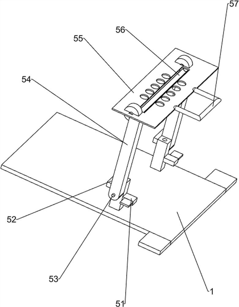
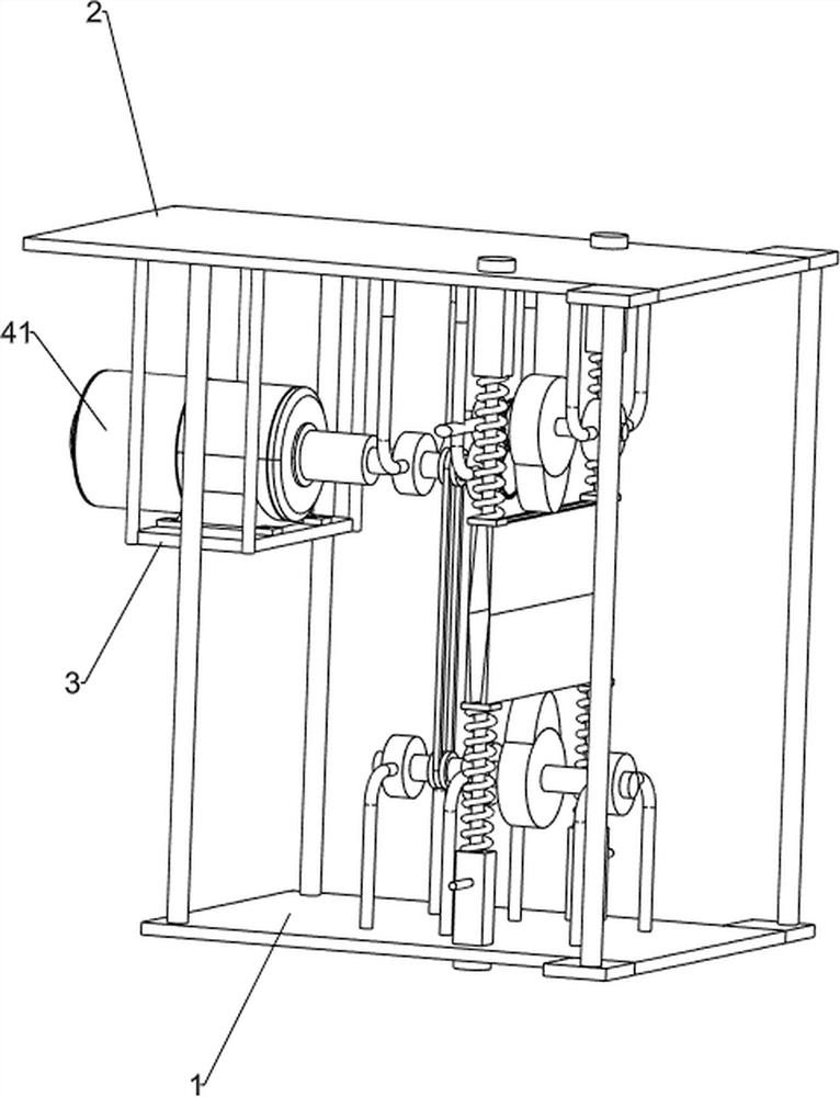
[0021] An injection molding removal device, such as figure 1 As shown, it includes a bottom frame 1, an upper plate 2, a support platform 3 and a cutting mechanism 4. The top of the bottom frame 1 is provided with an upper plate 2, and the left side of the bottom of the upper plate 2 is provided with a support platform 3. The top of the bottom frame 1 and the upper plate A cutting mechanism 4 is provided between the 2 bottoms.

[0022] When people want to use this device to cut off the finished product after injection molding, the finished product is manually put between a certain part of the cutting mechanism 4, and then a certain part of the cutting mechanism 4 is opened, and the cutting mechanism 4 cuts the finished product, and then A certain part of the cutting mechanism 4 is closed, and the finished product after cutting is collected.

Embodiment 2

[0024] On the basis of Example 1, such as figure 2 , image 3 , Figure 4 , Figure 5 and Figure 6 As shown, the cutting mechanism 4 includes a motor 41, a first transmission shaft 42, a second transmission shaft 43, a third transmission shaft 44, a transmission gear set 45, a pulley assembly 46, an upper cam 47, a lower cam 48, an upper cutting knife group 49. Lower cutting knife group 410, spring 411 and long rod 412, motor 41 is provided on the support table 3, the output shaft of motor 41 is provided with a first transmission shaft 42, and the first transmission shaft 42 rotates with the left side of the bottom of the upper plate 2 Type connection, the bottom right side of the upper plate 2 is provided with a third transmission shaft 44, the middle of the third transmission shaft 44 is provided with an upper cam 47, and a transmission is provided between the right end of the first transmission shaft 42 and the left part of the third transmission shaft 44. Gear set 45...


PUM


Abstract

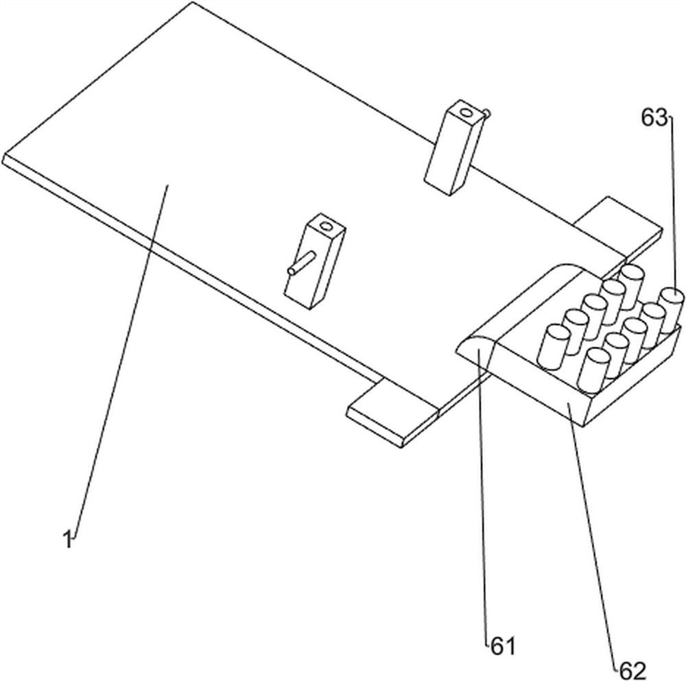
The invention relates to an excess material removing device, in particular to an injection molding excess material removing device. The injection molding excess material removing device can achieve automatic feeding, automatic discharging and automatic cutting and is high in safety. The injection molding excess material removing device comprises a bottom frame, an upper plate, a supporting table and a cutting mechanism; the upper plate is arranged at the top of the bottom frame; the supporting table is arranged at one side of the bottom of the upper plate; and the cutting mechanism is arrangedbetween the top of the bottom frame and the bottom of the upper plate. According to the injection molding excess material removing device, excess materials on injection-molded finished products can be cut off at a time through the cutting mechanism, so that the working efficiency of people is improved; through a feeding mechanism, people do not need to fix the positions of the finished products with hands, so that the hands of people are prevented from being hurt, and the safety of people is improved; and through a discharging mechanism, the cut finished products can be rapidly taken down, and the operation of the whole device is not delayed.

Description

technical field [0001] The invention relates to a material removal device, in particular to a material removal device for injection molding. Background technique [0002] Injection molding is a method of producing industrial products. Products usually use rubber injection molding and plastic injection molding. Injection molding is also called injection molding. It is a molding method of injection and molding. The advantage of injection molding method is that the production speed is fast. , high efficiency, automatic operation, and various shapes. After the injection molding is completed, the general injection molding machine will take out the finished product from the mold, and there will be some residual materials between the finished products. These residual materials need to be manually removed. [0003] People manually remove the remaining material, which is likely to be unclean. If you want to remove the remaining material, you must cut the injection molded product very...

Claims


Application Information

Patent Timeline
IPC IPC(8): B29C45/38B29C45/17B29C37/02
CPCB29C45/382B29C45/1753B29C45/1769B29C37/02
Inventor 唐斌
Owner 唐斌
Learn More