
Impressing equipment for metal product processing and using method of impressing equipment

A technology of metal products and imprinting equipment, which is applied in the field of metal product processing, can solve problems such as falling, synchronization of electric rotary blocks, affecting efficiency, etc., and achieve the effect of preventing accumulation or falling

Inactive Publication Date: 2021-01-19
浙江植言环境科技有限公司
View PDF1 Cites 0 Cited by
  • Summary
  • Abstract
  • Description
  • Claims
  • Application Information

AI Technical Summary

Problems solved by technology

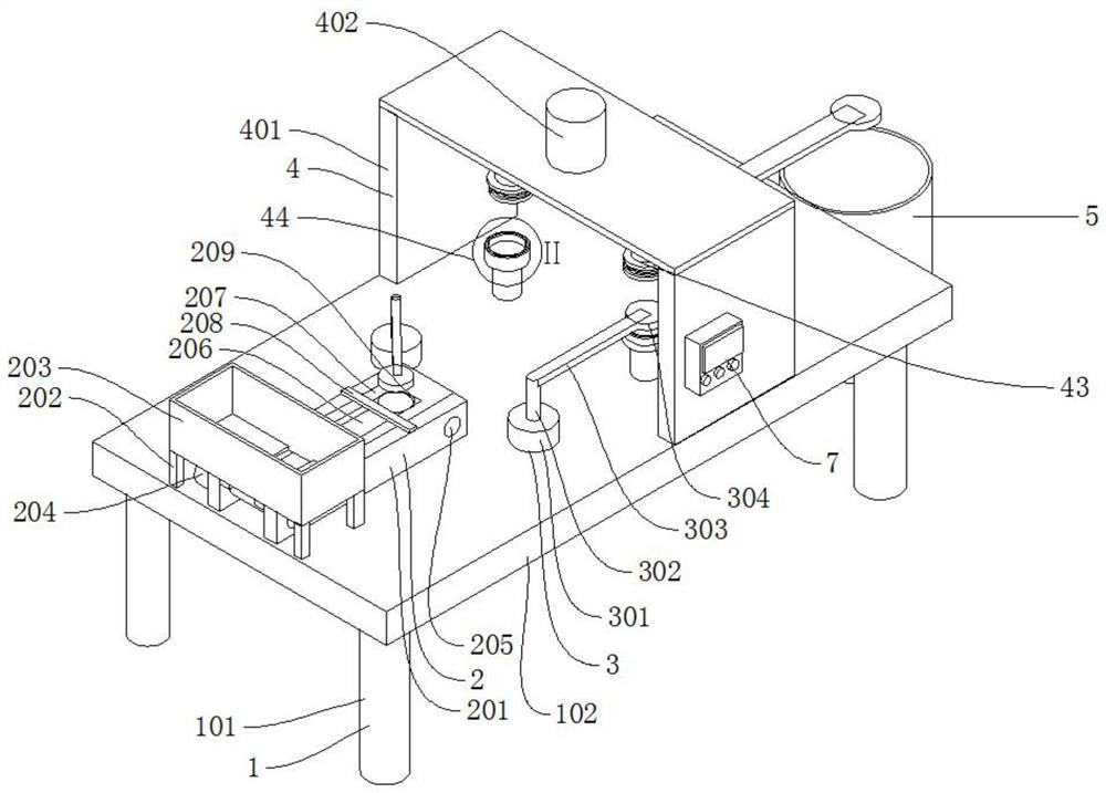
[0003] The existing authorized notification number is CN208469422U, which proposes a double-sided embossing device for metal product processing. The device includes a box, an embossing punch, an embossing die, a hydraulic cylinder, and a controller. The structure of the invention is reasonable. , equipped with an embossing punch and an embossing die, which can emboss metal products on both sides at one time, and are equipped with a first infrared sensor and a second infrared sensor, which can ensure that the embossing punch and the embossing die The absolute position between them can ensure the quality of the stamped metal products. The set punch mounting table and die mounting table and the embossing punch and embossing die are connected by bolts. When it is necessary to replace the new die It is convenient to replace the new embossing punch and embossing die when printing the pattern, but the loading and unloading of the device needs to be placed and retrieved manually. The manual placement of the material cannot be accurately synchronized with the electric rotary block, and the slow placement will affect the efficiency. , the material will fall from the conveyor belt if it is placed quickly

Method used


Image

  • Impressing equipment for metal product processing and using method of impressing equipment
  • Impressing equipment for metal product processing and using method of impressing equipment
  • Impressing equipment for metal product processing and using method of impressing equipment

Examples


Embodiment Construction

[0025] The following will clearly and completely describe the technical solutions in the embodiments of the present invention with reference to the accompanying drawings in the embodiments of the present invention. Obviously, the described embodiments are only some, not all, embodiments of the present invention.

[0026] In describing the present invention, it should be understood that the terms "upper", "lower", "front", "rear", "left", "right", "top", "bottom", "inner", " The orientation or positional relationship indicated by "outside", etc. is based on the orientation or positional relationship shown in the drawings, and is only for the convenience of describing the present invention and simplifying the description, rather than indicating or implying that the referred device or element must have a specific orientation, so as to Specific orientation configurations and operations, therefore, are not to be construed as limitations on the invention.

[0027] like Figure 1-Fi...


PUM


Abstract

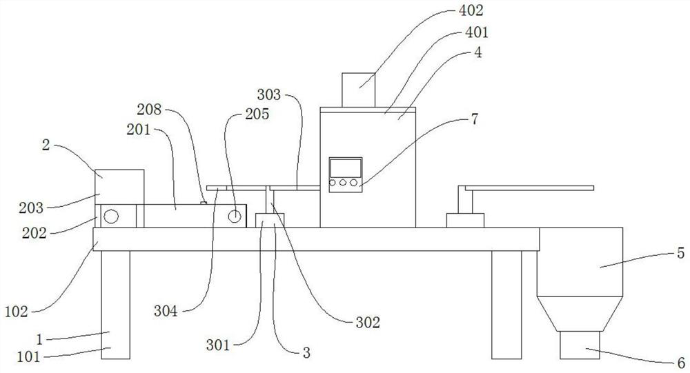
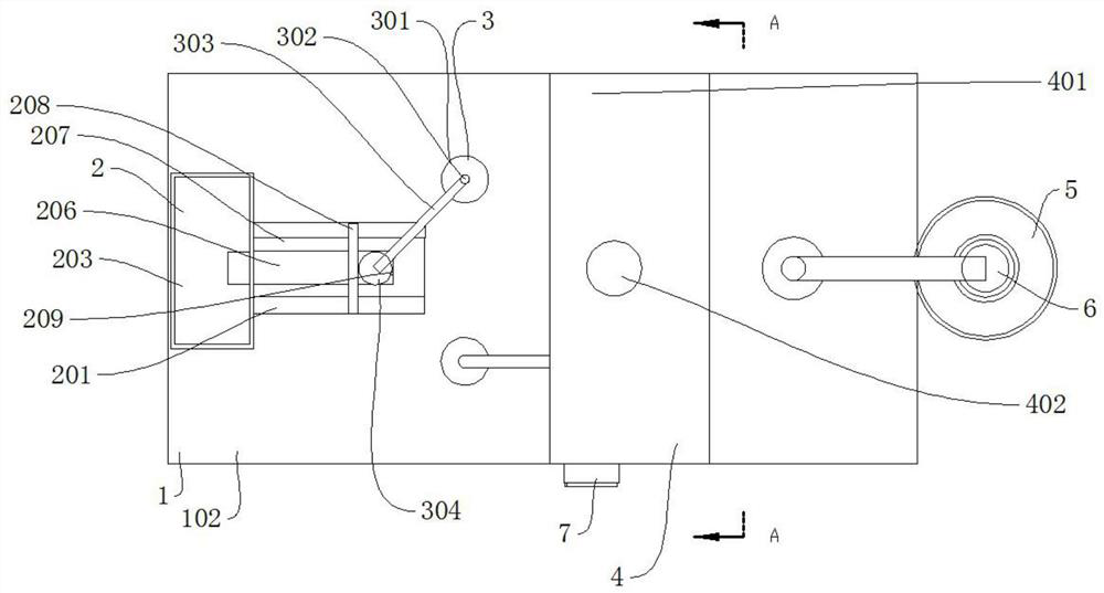
The invention discloses impressing equipment for metal product processing and a using method of the impressing equipment. The impressing equipment comprises a supporting mechanism, a transferring mechanism, an impressing mechanism, a guiding barrel, a quantifying barrel and a control box.The supporting mechanism is composed of supporting legs and a working plate, and the impressing equipment further comprises a feeding mechanism. The feeding mechanism comprises a supporting frame, fixing rods, a storage box, a motor, a rotating shaft, a conveying belt, a limiting plate, a baffle and a first pressure sensor. The arrangement of the storage box is beneficial to placing a large number of materials at a time, the arrangement of the conveying belt is beneficial to conveying the materials, the arrangement of the limiting plate is beneficial to the sequential arrangement and transportation of the materials, the arrangement of the baffle ensures the position of the next material when the transferring mechanism adsorbs the materials, the whole feeding mechanism realizes the automatic sequential arrangement and transportation of the materials, a waiting effect is achieved, and accumulation orfalling is prevented.

Description

technical field [0001] The invention relates to the technical field of metal product processing, in particular to an embossing device for metal product processing and a use method thereof. Background technique [0002] Embossing is to place the sheet material between the upper and lower molds, change the thickness of the material under the action of pressure, and fill the extruded material into the convex and concave parts of the mold cavity with undulating fine lines, while A forming method for forming undulating bulges and characters or patterns on the surface of metal products, such as coins and medals currently used, are all formed by embossing. [0003] The existing authorized notification number is CN208469422U, which proposes a double-sided embossing device for metal product processing. The device includes a box, an embossing punch, an embossing die, a hydraulic cylinder, and a controller. The structure of the invention is reasonable. , equipped with an embossing pun...

Claims


Application Information

Patent Timeline
IPC IPC(8): B44B5/00B44B5/02
CPCB44B5/0052B44B5/02B44B5/022B44B5/026
Inventor 徐承疆
Owner 浙江植言环境科技有限公司
Learn More