Supercharge Your Innovation With Domain-Expert AI Agents!

Mounting structure of handrail on tower crane standard joint platform and tower crane jacking cross beam

A technology of installation structure and standard section, which is applied in the direction of cranes, etc., can solve the problems that the probability of tower crane anti-dropping cannot be further improved, the connection force between the jacking beam and the standard section is not enough, and effective locking cannot be carried out.

Pending Publication Date: 2021-01-19
CHANGDE RONGCHENG MACHINERY CO LTD
View PDF0 Cites 0 Cited by
  • Summary
  • Abstract
  • Description
  • Claims
  • Application Information

AI Technical Summary

Problems solved by technology

[0004] In order to solve the problem of dislocation when two standard sections are docked with each other, a second operation must be performed to align the standard sections with each other, and the operation is very cumbersome; and when the existing tower crane beam is connected to the standard section, effective locking cannot be performed. Therefore, the connecting force between the jacking crossbeam and the standard section is not enough, and the probability of preventing the tower crane from falling off cannot be further improved. The purpose of the present invention is to provide the railing on the platform of the tower crane standard section and the tower crane jacking crossbeam installation structure

Method used


Image

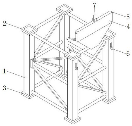
  • Mounting structure of handrail on tower crane standard joint platform and tower crane jacking cross beam
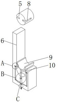
  • Mounting structure of handrail on tower crane standard joint platform and tower crane jacking cross beam
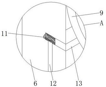
  • Mounting structure of handrail on tower crane standard joint platform and tower crane jacking cross beam

Examples


Embodiment Construction

[0029] The following will clearly and completely describe the technical solutions in the embodiments of the present invention with reference to the accompanying drawings in the embodiments of the present invention. Obviously, the described embodiments are only some, not all, embodiments of the present invention. Based on the embodiments of the present invention, all other embodiments obtained by persons of ordinary skill in the art without making creative efforts belong to the protection scope of the present invention.

[0030] In the description of the present invention, it should be noted that the terms "center", "upper", "lower", "left", "right", "vertical", "horizontal", "inner", "outer" etc. The indicated orientation or positional relationship is based on the orientation or positional relationship shown in the drawings, and is only for the convenience of describing the present invention and simplifying the description, rather than indicating or implying that the referred d...


PUM


Abstract

The invention discloses a mounting structure of a handrail on a tower crane standard joint platform and a tower crane jacking cross beam. The mounting structure comprises standard joints, a positioning mechanism, a clamping mechanism and a pneumatic transmission mechanism. An oil cylinder is mounted above one sides of the standard joints, and the output end of the oil cylinder is connected with amoving plate. By arranging the positioning mechanism, when the two standard joints are in butt joint, lower connecting plates and upper connecting plates are aligned with each other, in the process that the upper connecting plates and the lower connecting plates make contact with each other, extrusion plates are stressed to retract into first connecting grooves and drive second springs to be compressed, high-pressure inert gas in the first connecting grooves enters limiting holes through connecting holes, the air pressure in the limiting holes is increased, and therefore guide columns move downwards on the inner walls of the limiting holes till the guide columns are clamped into the inner walls of guide holes, and dislocation in the butt joint process of the two standard joints is prevented.

Description

technical field [0001] The invention relates to the field of tower cranes, in particular to a railing on a standard section platform of a tower crane and an installation structure for a tower crane jacking beam. Background technique [0002] Tower crane, also known as tower crane, is the most commonly used lifting equipment on construction sites, also known as "tower crane". The steel bar, wooden corrugated, concrete, steel pipe and other construction raw materials used, the tower crane is an indispensable equipment on the construction site. [0003] But at present, when the two standard sections of the tower crane are docked with each other, if misalignment occurs, a second operation must be performed to align the standard sections with each other, and the operation is very cumbersome; , effective locking cannot be performed, resulting in insufficient connection force between the jacking beam and the standard section, and the probability of preventing the tower crane from ...

Claims


Application Information

Patent Timeline
IPC IPC(8): B66C23/88B66C23/62
CPCB66C23/88B66C23/62
Inventor 李伟张力周游
Owner CHANGDE RONGCHENG MACHINERY CO LTD
Features
  • R&D
  • Intellectual Property
  • Life Sciences
  • Materials
  • Tech Scout
  • Unparalleled Data Quality
  • Higher Quality Content
  • 60% Fewer Hallucinations
Learn More