
Power distribution network overhead wire replacement method

A technology for overhead wires and replacement methods, which is applied in the direction of overhead lines/cable equipment, etc., and can solve the problem of inability to proceed smoothly, live work vehicles cannot be in place to cooperate with disassembly and assembly of fittings, and inability to mount and disassemble small side fittings and insulated wire fittings And other issues

Active Publication Date: 2021-01-19
ZHEJIANG DAYOU IND CO LTD HANGZHOU SCI TECH DEV BRANCH CO
View PDF13 Cites 1 Cited by
  • Summary
  • Abstract
  • Description
  • Claims
  • Application Information

AI Technical Summary

Problems solved by technology

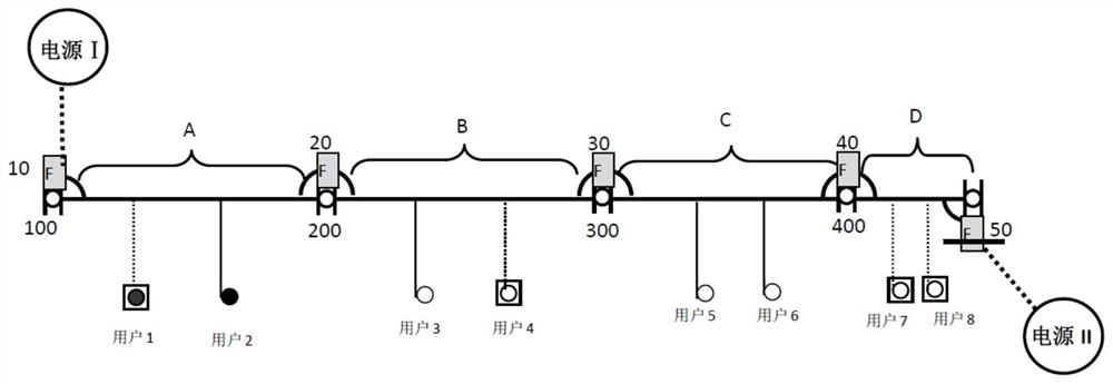
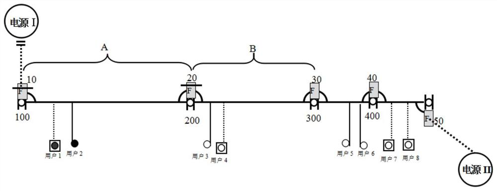
[0004] For the replacement of overhead bare wires with overhead insulated wires in a section between two section switches 10 and 20, there are the following problems: When the power supply I internal outlet cable interval switch and the 10, 20 switches are pulled, the section The large side of the switch 20 is electrified due to the reversing of the power supply II, and the large side of the tower 200 is electrified, so maintenance personnel cannot board the tower 200 to disassemble and assemble the small side fittings in order to hang the newly replaced insulated wire fittings. , the replacement work of the overhead line between the two section switches 10 and 20 cannot be completed
However, when this kind of live work coordination is carried out, it is easily affected by terrain conditions and meteorological conditions, and there is a possibility that the operation cannot be carried out and cannot be carried out smoothly.
[0006] Another solution is: since the on-site environment usually cannot meet the parking requirements of live working vehicles, it is not possible to replace the fittings on the 200 small side of the pole tower (the 20 small side lead wire of the section switch) during live work so as to hang the overhead For insulated wires, the overhead wires are generally replaced by expanding the power outage range, that is, disconnecting the power supply I internal outlet cable interval switch and the 10, 20 and 30 segment switches, and replacing the A-section overhead wires, but doing so will bring Two disadvantages: 1. It expands the scope of power outages, causing users 3 and 4 on the B segment outside the operating range to accompany the power outage, which reduces the reliability of power supply, reduces the satisfaction of users with electricity, and affects the power business environment
2. When the line in section A is replaced with an insulated line, the users on the line in section B are caused to have a power outage. In the case that the work vehicle cannot be in place to cooperate with the disassembly and assembly of fittings, the scope of power failure can only be expanded, and the 10, 20, 30, and 40 segment switches are disconnected to replace the overhead wires of the B segment
At this time, when the overhead wire of section A has been replaced in the previous period, user 1 and user 2 are disabled. At this time, due to the replacement of the overhead wire of section B, it will again cause user 1, user 2 of section A and user 5 and user 6 of section C. Accompanied parking, the result is that in addition to the increase of accompanying parking users within the range of C, users within the range of A and B will have repeated and frequent power outages, which seriously affects user satisfaction with electricity use

Method used


Image

  • Power distribution network overhead wire replacement method
  • Power distribution network overhead wire replacement method
  • Power distribution network overhead wire replacement method

Examples


Embodiment Construction

[0039] The technical solutions of the present invention will be further described below in conjunction with the accompanying drawings, but the present invention is not limited to these embodiments.

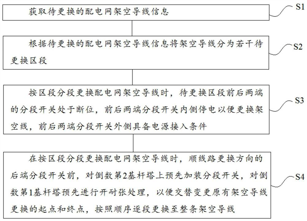
[0040] The basic idea of ​​the present invention is to use the newly opened tension rod as the wire for each section by installing the segment switch and the opening tension on the last two base towers in front of the rear end segment switch in the direction of line replacement in each section. The end point of the replacement and the starting point of the next section of the wire are replaced, avoiding the fact that the original sub-section switch is charged on one side and cannot climb the pole, which requires the cooperation of live work to cause additional maintenance links, which may cause delays in the construction period or construction on the day The resulting power outage plan is not rigidly implemented, which affects the normal production and living electricity demand of ...


PUM


Abstract

The invention relates to the field of power distribution network maintenance methods, in particular to a power distribution network overhead conductor replacement method which comprises the steps thatinformation of a to-be-replaced power distribution network overhead conductor is obtained; the overhead conductor is divided into a plurality of sections to be replaced according to the information of the overhead conductor of the power distribution network to be replaced; when the power distribution network overhead conductor is replaced sectionally according to the sections, the section switches at the front and rear ends of the to-be-replaced section are disconnected, the inner sides of the section switches at the front and rear ends are powered off to replace the overhead conductor, and the outer sides of the section switches at the front and rear ends have power access conditions; when the overhead conductor of the power distribution network is replaced sectionally according to sections and before a rear-end section switch in the line replacement direction, a section switch is additionally arranged on a penultimate base tower in advance, strain treatment is conducted on a penultimate base tower in advance, the starting point and the ending point of original overhead conductor replacement are alternately changed, and the overhead conductor is replaced to the whole overhead conductor according to the sequence. According to the method disclosed in the invention, all power-off operation in the section is realized, normal power utilization of users in other sections is not influenced, and the safety risk is controllable.

Description

technical field [0001] The invention relates to the field of distribution network maintenance methods, in particular to a method for replacing overhead conductors of a distribution network. Background technique [0002] With the continuous development of the national economy and the continuous advancement of urbanization and urbanization, more and more projects are replacing the original overhead bare wires of the distribution network with overhead insulated wires. On the one hand, the replacement of overhead insulated wires can reduce the operation failure of the distribution network Efficiency, improve the grid operation and maintenance level and power supply reliability, and at the same time, it can solve the contradiction between tree lines and beautify the urban landscape. [0003] Usually, in the above-mentioned replacement process of distribution network overhead conductors, considering the operators, equipment, safety risks, etc., it is necessary to control the workl...

Claims


Application Information

Patent Timeline
IPC IPC(8): H02G1/02
CPCH02G1/02
Inventor 焦建立刘欣宇向新宇张瑞赵斌炎石霄峰牟传强向俊楠
Owner ZHEJIANG DAYOU IND CO LTD HANGZHOU SCI TECH DEV BRANCH CO
Learn More