Box-type high-speed motor

A high-speed motor and box-type technology, applied in the direction of electrical components, electromechanical devices, electric components, etc., to achieve high stability, reduce fault sources, and simplify the rotor structure

Inactive Publication Date: 2021-01-19
WOLONG ELECTRIC NANYANG EXPLOSION PROTECTION GRP CO LTD +1
View PDF17 Cites 1 Cited by
  • Summary
  • Abstract
  • Description
  • Claims
  • Application Information

AI Technical Summary

Problems solved by technology

[0006] The technical solution focuses on improving the noise reduction of the motor, and does not involve the related structural improvements of the rotor and the motor to adapt to higher speed conditions

Method used


Image

  • Box-type high-speed motor
  • Box-type high-speed motor
  • Box-type high-speed motor

Examples


Embodiment Construction

[0033] The specific implementation manners of the present invention will be described in detail below in conjunction with the accompanying drawings.

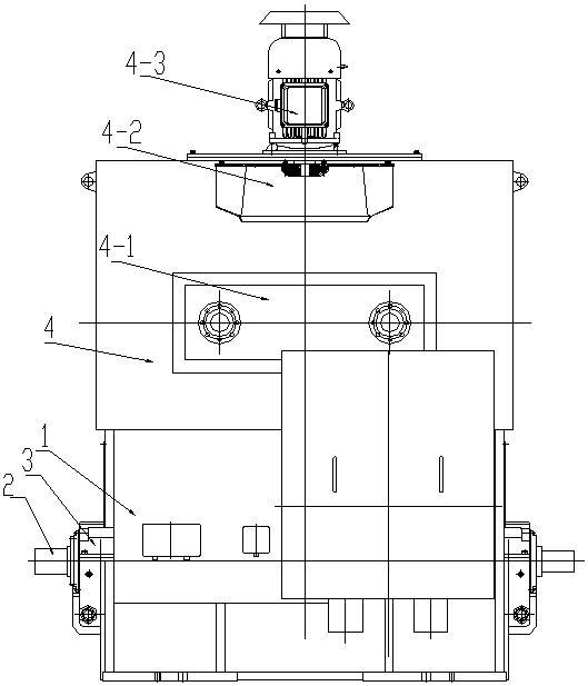
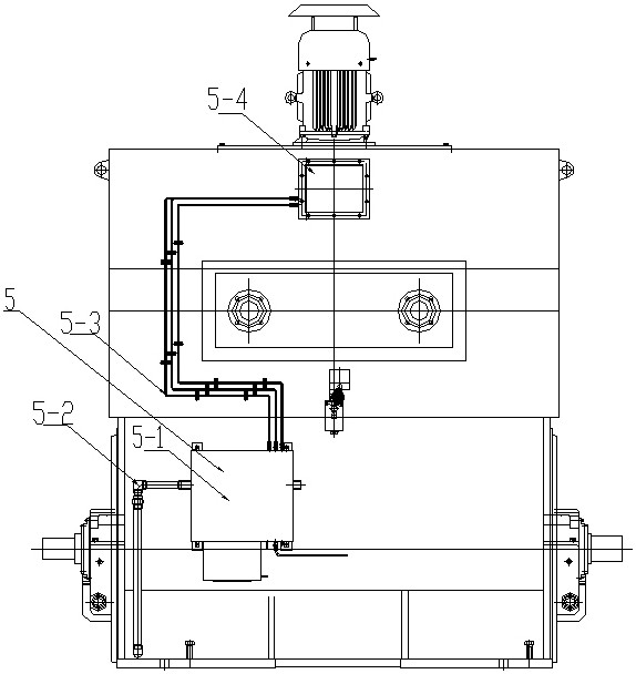
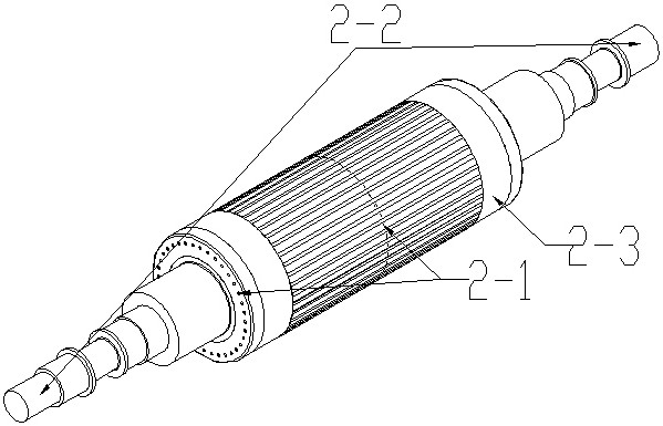
[0034] Such as Figure 1 to Figure 5 As shown, a box-type high-speed motor of the present invention is mainly composed of a box-type motor stator 1, a bearing 3 installed on the box-type motor stator frame, and a motor rotor 2 supported by the bearing. The cooler is located in the box type motor top.

[0035] In order to reduce harmonic loss, different from conventional motor rotor chute technology, the invention uses chute technology for the stator 1 core of the box-type motor, which can simplify the rotor structure.

[0036] The bearing 3 adopts a non-standard end cover type tilting pad bearing, the motor end cover 3-1 and the bearing seat 3-2 are of an integrated structure, and the motor end cover 3-1 is directly located under the bearing seat 3-2. Compared with the A-type bearings of conventional box-type motors, the axial...


PUM


Abstract

The invention discloses a box-type high-speed motor which is mainly composed of a box-type motor stator, a bearing installed on a box-type motor stator base and a motor rotor supported by the bearing,a cooler is located at the top of the box-type motor, and the motor rotor is of a solid rotor structure and is provided with balance areas at the two ends of a rotor body. The motor rotor is also provided with a balance area in the center of the rotor body. The box-type high-speed motor is compact in structure and reliable in operation, and is suitable for higher-rotating-speed working conditions.

Description

technical field [0001] The invention belongs to the technical field of high-speed motors, in particular to a box-type high-speed motor. Background technique [0002] In the field of high-speed motors, permanent magnet structures are generally used, and the motor capacity is small, which is not suitable for high-power applications. The capacity of conventional silicon steel sheet rotors can be relatively larger, but due to the influence of the structural strength of the rotor, it is not suitable for high speed applications. [0003] The invention of Publication No. CN111884379A relates to a cross-flow air-cooled rotor and a high-speed motor. The high-speed motor includes a casing, a hollow shaft, a permanent magnet rotor and a stator. The hollow shaft is hollow inside, and its two ends are respectively supported by bearings. In the shell, one end of the hollow shaft is open, and the other end is fixedly connected to the output shaft of the high-speed motor. The permanent mag...

Claims


Application Information

Patent Timeline
Patent Type & Authority Applications(China)
IPC IPC(8): H02K7/04H02K1/22H02K1/16H02K1/28H02K7/08H02K5/16H02K7/00H02K5/20H02K5/136
CPCH02K1/165H02K1/22H02K1/28H02K5/136H02K5/16H02K5/20H02K7/003H02K7/04H02K7/08H02K2205/09
Inventor 周少正万创奇赵岩王成硕吴宣东张磊张东波
Owner WOLONG ELECTRIC NANYANG EXPLOSION PROTECTION GRP CO LTD
Why Eureka
Try Eureka