Eureka AIR delivers breakthrough ideas for toughest innovation challenges, trusted by R&D personnel around the world.

Circuit board structure and manufacturing method thereof

A circuit board and circuit technology, which is used in the manufacture of printed circuits, printed circuits, and assembling printed circuits with electrical components.

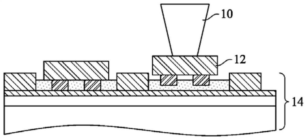
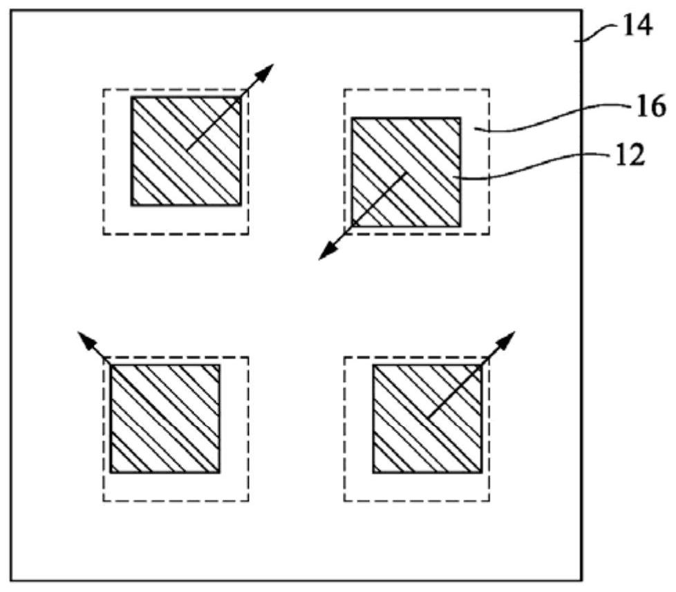
Active Publication Date: 2021-01-19
UNIMICRON TECH CORP
View PDF5 Cites 0 Cited by
  • Summary
  • Abstract
  • Description
  • Claims
  • Application Information

AI Technical Summary

Problems solved by technology

[0005] The purpose of the present invention is to overcome the defects of the existing circuit board structure, that is, the deviation of the electronic components from the predetermined position in the carrier board will cause the guide holes or circuit layers formed in the subsequent manufacturing process to be unable to be accurately processed, and provide A new circuit board structure and its manufacturing method, the technical problem to be solved is to change the placement offset of electronic components, making it more suitable for practical

Method used


Image

  • Circuit board structure and manufacturing method thereof
  • Circuit board structure and manufacturing method thereof
  • Circuit board structure and manufacturing method thereof

Examples


Embodiment Construction

[0080] The ensuing disclosure provides many different implementations or examples for implementing different features of the presented subject matter. Specific embodiments of components and configurations are described below to simplify the present disclosure. These are of course only examples and are not intended to be limiting. For example, in the description that follows, a first feature is formed on or over a second feature, may include embodiments in which the first and second features are formed in direct contact, and may also include additional features formed on the first and second features. Between two features, therefore the first and second features may not be in direct contact embodiments. Furthermore, the present disclosure may repeat numbers and / or letters in various embodiments. Such repetition is for simplicity and clarity and is not intended to imply a relationship between the various embodiments and / or configurations discussed.

[0081] Furthermore, to fa...


PUM


Abstract

The invention relates to a circuit board structure and a manufacturing method thereof. The circuit board structure comprises a circuit layer structure, an electronic element and a positioning piece. Aline layer structure includes a plurality of dielectric layers and lines in the dielectric layers. The electronic component is arranged in the circuit layer structure and comprises a wafer and a conductive protruding block, the wafer is provided with a first surface and a second surface which are oppositely arranged, the first surface of the wafer makes contact with one dielectric layer in the multiple dielectric layers, and the conductive protruding block is arranged on the second surface of the wafer and electrically connected with the wafer. The positioning piece is arranged in the circuitlayer structure and abuts against the conductive protruding block. The invention also provides a manufacturing method of the circuit board structure. According to the technical scheme, the accuracy of placing the electronic element can be improved.

Description

technical field [0001] The present disclosure relates to a circuit board structure with electronic components, especially a circuit board structure with embedded electronic components. Background technique [0002] In the conventional manufacturing technology of circuit boards with embedded electronic components, when the electronic components are placed on the substrate, the placement accuracy is affected by the placement device, and each electronic component is randomly offset. [0003] see Figure 1A and Figure 1B , respectively showing a cross-sectional view and a bottom view of a conventional circuit board structure. like Figure 1A As shown, the placement device 10 is deflected when placing the wafer 12 on the substrate 14 . Figure 1B The misalignment between the wafer 12 and the wafer placement area 16 of the substrate 14 is displayed. [0004] The deviation of the electronic components from the predetermined positions in the carrier board may cause the via holes...

Claims


Application Information

Patent Timeline
IPC IPC(8): H05K3/30H05K3/32
CPCH05K3/301H05K3/321
Inventor 林建辰
Owner UNIMICRON TECH CORP
Why Eureka
Eureka Blog
Learn More