Stator for a rotating electrical machine
A technology for rotating electrical machines and stators, used in the manufacture of motor generators, prefabricated windings embedded in motors, electromechanical devices, etc., can solve problems such as hindering machine operation and disengagement, to simplify tools, reduce the risk of loss, and reduce the need for cleaning. Effect
- Summary
- Abstract
- Description
- Claims
- Application Information
AI Technical Summary
Problems solved by technology
Method used
Image

Examples
Embodiment Construction
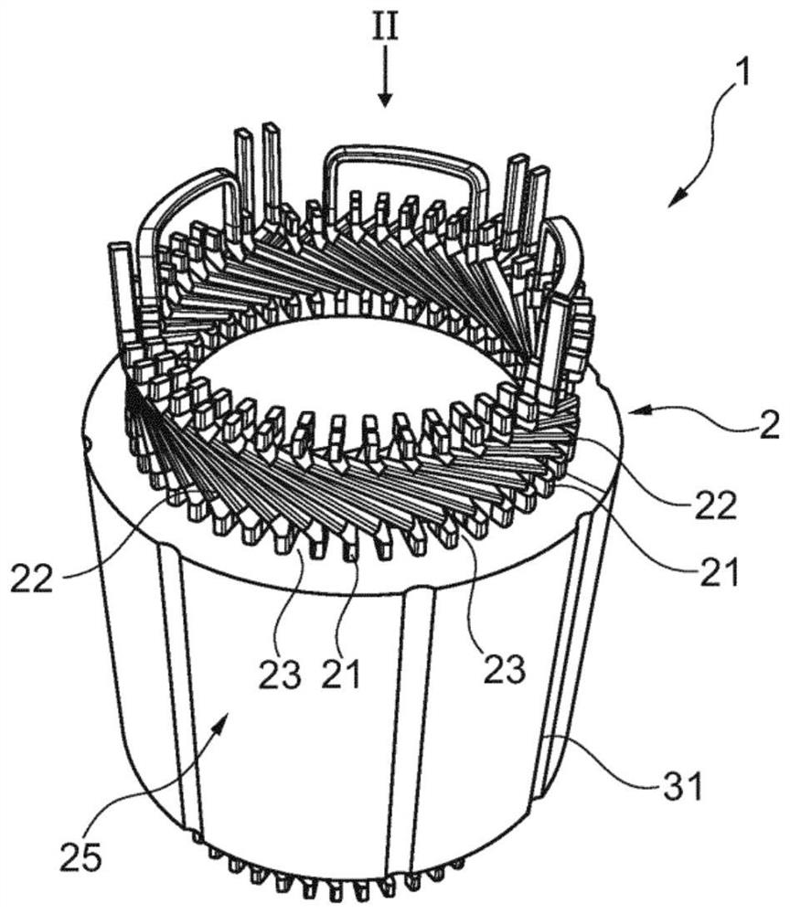
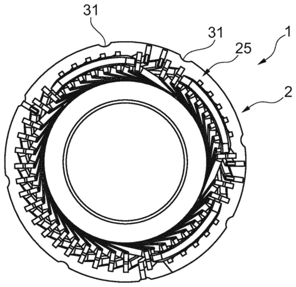
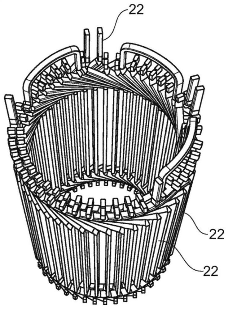
[0115] Figure 1 to Figure 6 A stator 2 of a rotating electric machine 1 is shown, which also has a not shown rotor. In the case of a synchronous motor, the stator can generate a rotating magnetic field that drives the rotor, while in the case of an alternator, the rotation of the rotor induces an electromotive force in the electrical conductors of the stator.
[0116] The examples illustrated below are schematic and do not necessarily consider the relative sizes of the respective constituent elements.
[0117] The stator 2 has electrical conductors 22 arranged in slots 21 formed between teeth 23 of a stator mass 25 . The notches 21 are closed, ie a complete circuit can be formed around each slot 21 without encountering cutouts in the stator mass. The slots 21 are closed on the air-gap side by material bridges 27 and on the opposite side by yokes 29 , each material bridge 27 connecting two consecutive teeth of the stator mass 25 . Yoke 29 and tooth 23 are in one piece. If ...
PUM
 Abstract
Description
Claims
Application Information