Medical aid device
A medical rescue and storage tank technology, applied in the field of medical rescue equipment, can solve the pain of the wounded, needle rolling, affecting the efficiency of intravenous injection and other problems, to achieve the effect of preventing road bumps, reducing technical difficulty, and reducing the difficulty of injection
- Summary
- Abstract
- Description
- Claims
- Application Information
AI Technical Summary
Problems solved by technology
Method used
Image

Examples
Embodiment 1
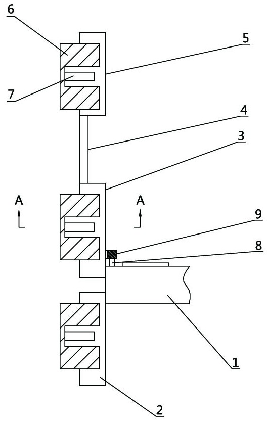
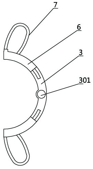
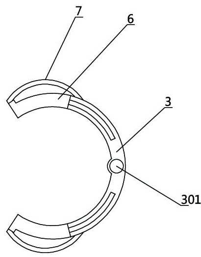
[0021]Example 1: Refer toFigure 1-6 , A medical rescue device, comprising a first limit plate 2, a first limit plate 3, a third limit plate 5, the first limit plate 2, the first limit plate 3, the third limit plate 5 cross-section They are all semi-circular arc structures, and the central axes of the first limit plate 2, the first limit plate 3, and the third limit plate 5 coincide. The first limit plate 2 and the first limit plate 3 are both fixed on the One end of a connecting rod 1, the first connecting rod 1 is fixed on the bed of the wounded, the first limiting plate 3 is fixedly connected to the third limiting plate 5 through the second connecting rod 4, the first limiting plate 2, the first limiting plate The sliding slots on the front and rear sides of the positioning plate 3 and the third limiting plate 5 are slidably connected with a movable card plate 6, and the movable card plate 6 passes through the first elastic piece 7 and the first limit plate 2 in the corresponding ...
Embodiment 2
[0023]Example 2, seeFigure 7-8On the basis of embodiment 1, the first connecting rod 1 is connected to one end of the first sliding shaft 19 of the stretcher through a rolling bearing. The stretcher includes two first stretcher cloths 21, two second stretcher cloths 22, and four first stretcher cloths. The winding roller 23, the four second winding rollers 24, and the two first fixing plates 11 are each provided with a second fixing plate 17 on both sides of the first fixing plate 11, and the second fixing plate 17 faces away from the first fixing plate. A handle 16 is provided on one side of a fixed plate 11, a push-pull pin 13 is provided on the handle 16 on one of the second fixed plates 17 corresponding to the first fixed plate 11, and each first fixed plate 11 is rotatably connected with Two transmission wheels 18, the two transmission wheels 18 located on the same first fixed plate 11 are connected by a conveyor belt, and the first receipt rollers 23 are fixedly connected to t...
PUM
 Abstract
Description
Claims
Application Information