Reinforced concrete crusher

A reinforced concrete and pulverizer technology, applied in mechanical equipment, using liquid separating agent, solid separation and other directions, can solve the problems of time-consuming and laborious recycling of steel bars, easy occurrence of a large amount of dust, inconvenience in recycling steel bars, etc. The effect of improving the crushing effect and crushing efficiency, and improving the service life

Inactive Publication Date: 2021-01-22
岑泽江
View PDF0 Cites 2 Cited by
  • Summary
  • Abstract
  • Description
  • Claims
  • Application Information

AI Technical Summary

Problems solved by technology

[0002] Compared with concrete, the tensile strength of steel bars is very high, so people usually add reinforcement materials such as steel bars to the concrete to work together, the steel bars bear the tension, and the concrete bears the compressive stress; secondly, there is a good relationship between the steel bars and the concrete. Sometimes the surface of the steel bar is also processed into spaced ribs (called deformed steel bar) to improve the mechanical engagement between the concrete and the steel bar, but this is still not enough to transmit the tension between the steel bar and the concrete, although greatly It improves the firmness of reinforced concrete, but it also causes a lot of trouble when the building is demolished. After the steel bar is mixed with the concrete, the steel bar is stuck in the concrete. When the building is demolished, the broken concrete is often firmly attached to the steel bar. It is difficult to crush and recycle. The traditional pulverizer is easy to be damaged by the steel bar. The crushing efficiency is slow. The traditional pulverizer is difficult to separate the steel bar from the concrete. The operation is complicated, and the device is not convenient for the steel bar when crushing the reinforced concrete Recycling, manual recycling of steel bars is time-consuming and labor-intensive, and the device is prone to a lot of dust after the concrete is broken, which affects the working environment

Method used


Image

  • Reinforced concrete crusher
  • Reinforced concrete crusher
  • Reinforced concrete crusher

Examples


Embodiment 1

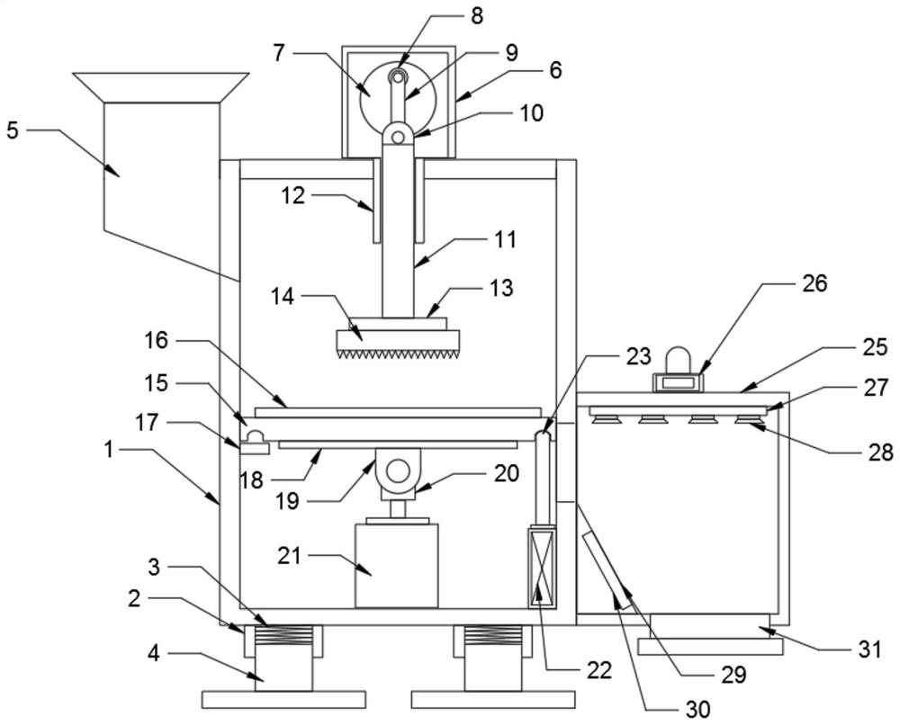
[0022] see Figure 1~3 , in an embodiment of the present invention, a pulverizer for reinforced concrete includes a crushing box 1, a discharge box 25 and a crushing hammer 14, a cylinder 2 is installed at the bottom of the crushing box 1, and a spring 3 is installed inside the cylinder 2 , the base 4 is installed at the bottom of the spring 3, and there are four cylinders 2, springs 3 and base 4, which are divided into four groups and evenly distributed at the four corners of the bottom of the crushing box 1. The cylinder 2, spring 3 and base 4 , can effectively slow down the vibration of the crushing box 1, and improve the service life of the crushing box 1; the upper left side of the crushing box 1 is provided with a feed port 5, and a motor frame 6 is installed in the middle of the top of the crushing box 1, and a second motor frame is installed inside the motor frame 6. Motor 32, rotating disk 7 is installed on the front end of second motor 32 rotating shafts, and rotatin...

Embodiment 2

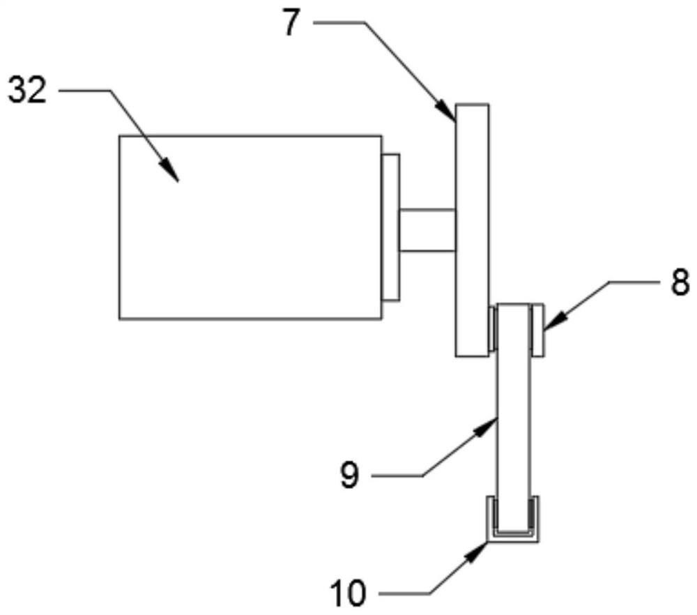
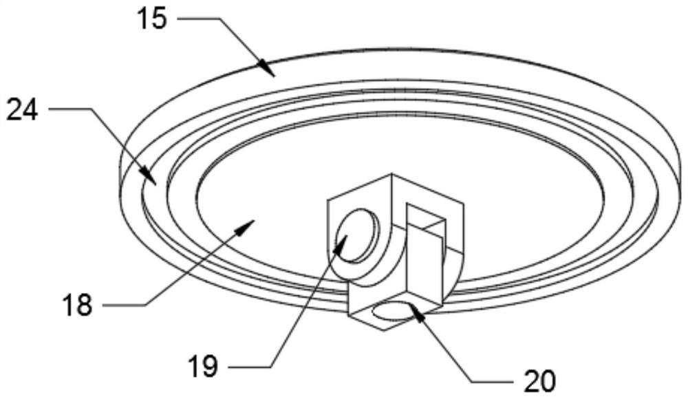
[0026] see Figure 4 , in an embodiment of the present invention, a pulverizer for reinforced concrete includes a crushing box 1, a discharge box 25 and a crushing hammer 14, a cylinder 2 is installed at the bottom of the crushing box 1, and a spring 3 is installed inside the cylinder 2 , the base 4 is installed at the bottom of the spring 3, the upper left side of the crushing box 1 is provided with a feed port 5, the middle part of the top of the crushing box 1 is equipped with a motor frame 6, and the inner side of the motor frame 6 is equipped with a second motor 32, the second motor 32 shaft The front end is equipped with a turntable 7, the edge of the turntable 7 is equipped with a rotating shaft 8, the outer side of the rotating shaft 8 is equipped with a connecting rod 9, the bottom end of the connecting rod 9 is equipped with a first fixed frame 10, and the bottom end of the first fixed frame 10 is equipped with a long rod 11 , the outer side of the long rod 11 is pro...

Embodiment 3

[0028]In the embodiment of the present invention, a pulverizer for reinforced concrete includes a crushing box 1, a discharge box 25 and a crushing hammer 14. A cylinder 2 is installed at the bottom of the crushing box 1, and a spring 3 is installed inside the cylinder 2. The base 4 is installed on the bottom of the spring 3, the upper left side of the crushing box 1 is provided with a feed port 5, the middle part of the top of the crushing box 1 is installed with a motor frame 6, the inner side of the motor frame 6 is installed with a second motor 32, and the front end of the second motor 32 shaft Rotating disk 7 is installed, rotating shaft 8 is installed on the edge of rotating disk 7, and connecting rod 9 is installed on the outer side of rotating shaft 8, and the bottom end of connecting rod 9 is installed with the first fixed frame 10, and the bottom end of the first fixed frame 10 is equipped with long rod 11, The outer side of the long rod 11 is provided with a limit tu...


PUM


Abstract

The invention discloses a reinforced concrete crusher comprising a crushing box, a discharging box and a crushing hammer, a motor frame is installed in the middle of the top end of the crushing box, asecond motor is installed on the inner side of the motor frame, a rotary disc is installed at the front end of a rotary shaft of the second motor, a rotating shaft is installed on the edge of the rotary disc, and a connecting rod is installed on the outer side of the rotating shaft; a first fixing frame is installed at the bottom end of the connecting rod, a long rod is installed at the bottom end of the first fixing frame, a limiting cylinder is arranged on the outer side of the long rod, and a connecting block and the crushing hammer are installed at the bottom end of the long rod. A supporting plate is arranged below the crushing hammer, a buffer pad is installed on the surface of the upper end of the supporting plate, a connecting plate is installed in the middle of the bottom end ofthe supporting plate, a second fixing frame is installed at the bottom end of the connecting plate, and a fixing block is installed on the inner side of the second fixing frame; a first motor is installed on the middle of the bottom end of the inner side of the crushing box, and the front end of a rotary shaft of the first motor is connected to the fixing block; the discharging box is arranged onthe right side of the crushing box. The reinforced concrete crusher is reasonable in structure, reinforced concrete can be crushed conveniently, and the crushing effect and the crushing efficiency areeffectively improved.

Description

technical field [0001] The invention relates to the technical field of concrete treatment, in particular to a pulverizer for reinforced concrete. Background technique [0002] Compared with concrete, the tensile strength of steel bars is very high, so people usually add reinforcement materials such as steel bars to the concrete to work together, the steel bars bear the tension, and the concrete bears the compressive stress; secondly, there is a good relationship between the steel bars and the concrete. Sometimes the surface of the steel bar is also processed into spaced ribs (called deformed steel bar) to improve the mechanical engagement between the concrete and the steel bar, but this is still not enough to transmit the tension between the steel bar and the concrete, although greatly It improves the firmness of reinforced concrete, but it also causes a lot of trouble when the building is demolished. After the steel bar is mixed with the concrete, the steel bar is stuck in ...

Claims


Application Information

Patent Timeline
Patent Type & Authority Applications(China)
IPC IPC(8): B02C1/14B02C23/00B02C23/10B02C23/20B01D47/06B03C1/02F16F15/067
CPCB01D47/06B02C1/14B02C23/00B02C23/10B02C23/20B02C2201/02B03C1/02F16F15/067
Inventor 岑泽江
Owner 岑泽江
Why Eureka
Try Eureka