Dust removal device for bag production

A dust removal device, luggage technology, applied in the direction of dry gas arrangement, cleaning method and utensils, cleaning hollow objects, etc., can solve the problems of low efficiency, waste of manpower, and no relief, so as to ensure the completion rate, improve work efficiency, and produce products neat effect

Pending Publication Date: 2021-01-22
湖南省俊华箱包制造有限公司
9 Cites 0 Cited by

AI-Extracted Technical Summary

Problems solved by technology

[0003] Among them, in the production site of luggage, there is often a certain amount of dust in the environment, and the generation of dust will greatly reduce the appearance of the product and affect sales. Therefore, the product often needs to be dedusted before leaving the factory. The dust removal ...

Method used

During specific use, fill up water for storage tank 5 by water tank mouth 6, and connect power supply for water pump 8 and air pump 20, select the upper adsorption roller 13 of suitable size, side adsorption roller 14 and lower adsorption roller 15 to be installed on support 12, you can start working, put the untreated product on the roller 21 on the side of the pretreatment component 2 of the workbench 1 and push it in, the product passes under the outlet pipe 9, and the clean water is evenly sprayed through the atomizing nozzle 11 On the surface of the product, a layer of water mist is formed to absorb the dust on the surface of the product and prevent the dust from drifting...

Abstract

The invention discloses a dust removal device for bag production comprising a workbench, a pretreatment assembly, an adsorption assembly and an air drying assembly, the workbench is arranged on the ground, the pretreatment assembly is arranged at one end of the workbench, the adsorption assembly is arranged in the middle of the workbench, and the air drying assembly is arranged at the other end ofthe workbench; wherein the pretreatment assembly comprises a water storage tank, a water tank opening, a water inlet pipe, a water pump, a water outlet pipe, a spraying pipe and an atomizing nozzle,the adsorption assembly comprises a support, an upper adsorption roller, a side adsorption roller and a lower adsorption roller, and the air drying assembly comprises a protective cover, an air outletpipe, an air outlet, an air conveying pipe and an air pump. The invention relates to the technical field of bag production, in particular to a dust removal device for bag production, which can removedust on the surface of a product, can adsorb the dust, is convenient to operate automatically and improves the working efficiency.

Application Domain

Drying solid materials without heatHollow article cleaning +1

Technology Topic

Process engineeringWater storage tank +6

Image

  • Dust removal device for bag production
  • Dust removal device for bag production

Examples

  • Experimental program(1)

Example Embodiment

[0015]The following will clearly and completely describe the technical solutions in the embodiments of the present invention with reference to the accompanying drawings in the embodiments of the present invention. Obviously, the described embodiments are only a part of the embodiments of the present invention, not all the embodiments; The embodiments of the present invention, and all other embodiments obtained by those of ordinary skill in the art without creative work, fall within the protection scope of the present invention.
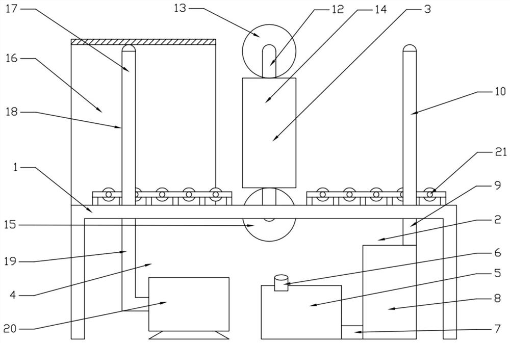
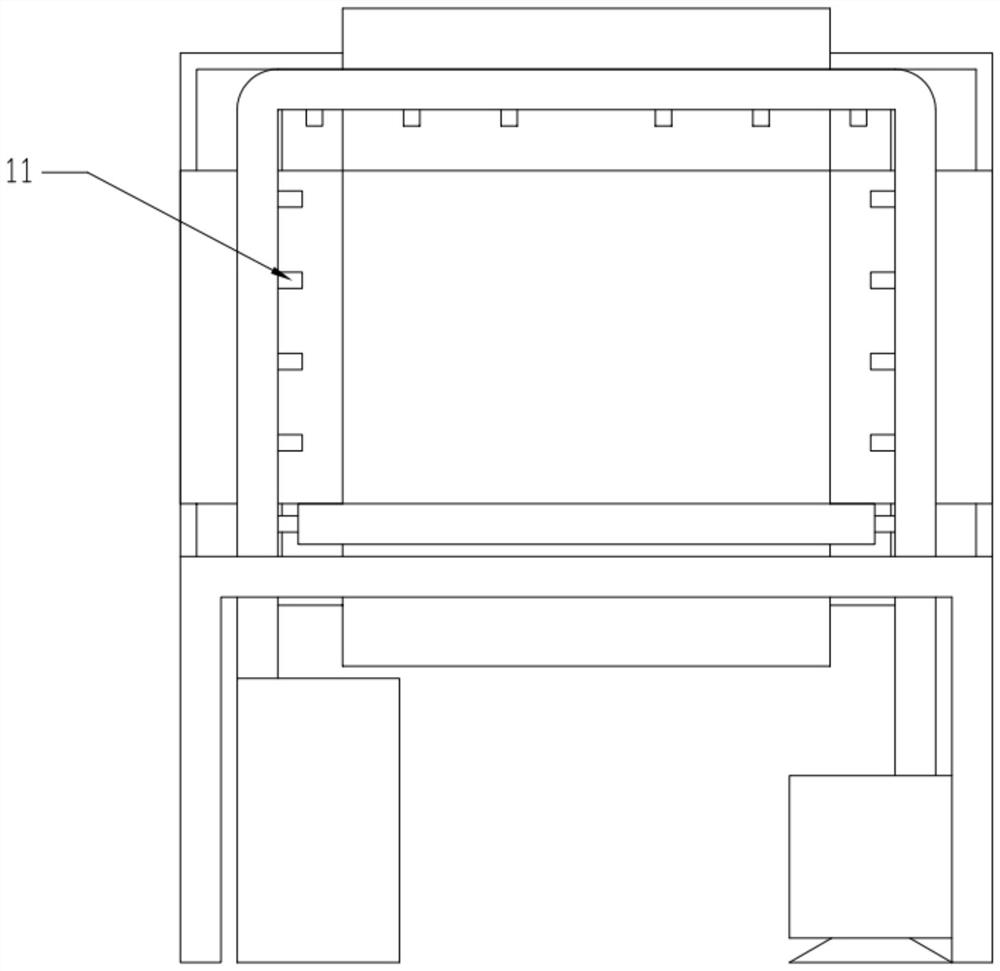
[0016]Such asFigure 1-2As shown, a dust removal device for luggage production of the present invention includes a workbench 1, a pretreatment assembly 2, an adsorption assembly 3, and an air-drying assembly 4. The workbench 1 is set on the ground, and the pretreatment assembly 2 is set on the workbench. One end of the table 1, the adsorption assembly 3 is set at the middle position of the workbench 1, the air drying assembly 4 is set at the other end of the workbench 1, the pretreatment assembly 2 includes a water storage tank 5, a water tank mouth 6, and a water inlet pipe 7. The water pump 8, the water outlet pipe 9, the spray pipe 10 and the atomizing nozzle 11, the water storage tank 5 is provided under the workbench 1, the water tank port 6 is provided on the water storage tank 5, and one end of the water inlet pipe 7 is provided at The water storage tank 5 is located at the bottom of the water storage tank 5, the other end of the water inlet pipe 7 is located on the water pump 8, the water pump 8 is located below the workbench 1 and is located beside the water storage tank 5, and one end of the water outlet pipe 9 is located On the water pump 8, the other end of the outlet pipe 9 penetrates the workbench 1 and is connected to one end of the spray pipe 10. The atomization nozzles 11 are evenly distributed on the inner and outer wall of the spray pipe 10. The adsorption assembly 3 includes a bracket 12 , The upper suction roller 13, the side suction roller 14 and the lower suction roller 15, the bracket 12 is arranged in the middle of the workbench 1, the upper suction roller 13 can be rotatably arranged above the bracket 12, the side suction roller 14 can be symmetrical It is rotatably arranged on both sides of the bracket 12. The lower suction roller 15 is rotatably arranged under the bracket 12 and penetrates the workbench 1. The air drying assembly 4 includes a protective cover 16, an air outlet tube 17, an air outlet 18, and an air pipe 19 and the air pump 20, the protective cover 16 is arranged on the workbench 1, the air outlet pipe 17 is arranged in the protective cover 16 and on the workbench 1, the air outlet 18 is evenly arranged on the inner and outer wall of the air outlet pipe 17 One end of the air pipe 19 penetrates the workbench 1 and is connected to one end of the air outlet pipe 17, and the other end of the air pipe 19 is connected to the air pump 20, and the air pump 20 is set under the workbench 1.
[0017]Wherein, there are rollers 21 on both sides of the worktable 1, and the rollers 21 are respectively arranged below the water outlet pipe 9 and the air outlet pipe 17; the upper adsorption roller 13, the side adsorption roller 14 and the lower adsorption roller 15 are The upper suction roller 13, the side suction roller 14 and the lower suction roller 15 are arranged on the surface of the blended fiber; the upper suction roller 13, the side suction roller 14 and the lower suction roller 15 are arranged in multiple sizes.
[0018]In specific use, fill the water storage tank 5 through the water tank port 6, and connect the power supply to the water pump 8 and the air pump 20. The upper adsorption roller 13, the side adsorption roller 14 and the lower adsorption roller 15 of suitable size are selected and installed on the bracket 12. You can start working. Put the untreated product on the roller 21 on the side of the pretreatment assembly 2 of the workbench 1 and push it in. The product passes under the outlet pipe 9, and the purified water is evenly sprayed on the surface of the product through the atomizing nozzle 11 , Forming a layer of water mist to absorb the dust on the surface of the product to prevent the dust from scattering. Then the product passes through the adsorption assembly 3, and under the action of the upper adsorption roller 13, the side adsorption roller 14 and the lower adsorption roller 15, the product surface Dust and moisture are adsorbed to achieve the purpose of dust removal, and then reach the idler 21 on the side of the air-drying assembly 4 of the workbench 1, the gas generated by the air pump 20 passes through the air pipe 19, the air outlet 17 and the air outlet 18 to air dry the product surface and blow After removing the residual substances, the product can be stored after the dust removal work is completed.
[0019]The present invention and its embodiments are described above, and this description is not restrictive. What is shown in the drawings is only one of the embodiments of the present invention, and the actual structure is not limited to this. In a word, if a person of ordinary skill in the art receives its enlightenment and does not deviate from the inventive purpose of the present invention, without creative design, structural modes and embodiments similar to the technical solution should belong to the present invention.

PUM

no PUM

Description & Claims & Application Information

We can also present the details of the Description, Claims and Application information to help users get a comprehensive understanding of the technical details of the patent, such as background art, summary of invention, brief description of drawings, description of embodiments, and other original content. On the other hand, users can also determine the specific scope of protection of the technology through the list of claims; as well as understand the changes in the life cycle of the technology with the presentation of the patent timeline. Login to view more.

Similar technology patents

Method of determining called numbers of intelligent service telephone bill and system thereof

InactiveCN101527898AGuaranteed completion rateExtend the time required to connect
Owner:ZTE CORP

Report data generating method and system

ActiveCN103473342ASimplify the docking processImprove work efficiency
Owner:BEIJING JOIN CHEER SOFTWARE

Automatic device for welding and detecting lithium battery

ActiveCN103904367AShorten the running distanceImprove work efficiency
Owner:DONGGUAN HONBRO LI BATTERY EQUIP TECH

Vacuum cleaner

InactiveCN103356140Aprevent liftingImprove work efficiency
Owner:SUZHOU HAAN TECH +1

Caking fertilizer crushing device for agriculture big data

Owner:安徽众力农业装备科技有限公司

Classification and recommendation of technical efficacy words

  • Guaranteed Completion Rate

Method of determining called numbers of intelligent service telephone bill and system thereof

InactiveCN101527898AGuaranteed completion rateExtend the time required to connect
Owner:ZTE CORP
Why Eureka
Try Eureka