Notched steel plate punching equipment for buildings

A technology for stamping equipment and construction, applied in the field of notched steel plate stamping equipment for construction, can solve the problems of affecting stamping, easy to get stuck in stamping parts, not easy to fall, etc., and achieve the effect of good corrosion resistance and high toughness

Inactive Publication Date: 2021-01-22
李冰娜
View PDF0 Cites 12 Cited by
  • Summary
  • Abstract
  • Description
  • Claims
  • Application Information

AI Technical Summary

Problems solved by technology

[0003] After the steel plate is produced, it needs to be processed into various shapes and then installed in different machines. One of the notched steel plates is an indispensable material in the construction field. At present, people are punching notches When forming steel plates, people often manually place the steel plate raw materials in the stamping machine, and then stamp the steel plate through the stamping machine. However, this stamping method has certain shortcomings. After the steel plate is stamped, it is easier to get stuck on the stamping parts. It is not easy to drop, which may affect the subsequent stamping, and requires people to continuously load the steel plate

Method used


Image

  • Notched steel plate punching equipment for buildings
  • Notched steel plate punching equipment for buildings
  • Notched steel plate punching equipment for buildings

Examples


Embodiment 1

[0023] A notch-shaped steel plate stamping equipment for construction, such as figure 1 , figure 2 , image 3 , Figure 4 and Figure 5 As shown, it includes a bottom plate 1, an L-shaped rod 2, a cylinder 3, a stamping block 4, a shaping mechanism 5, a feeding mechanism 6 and a discharging mechanism 7, and the middle part of the bottom plate 1 is fixedly connected with an L-shaped rod 2 and an L-shaped rod 2. Cylinder 3 is installed on the top, and the bottom end of the piston rod of cylinder 3 is connected with stamping block 4. A shaping mechanism 5 is arranged in the middle of the top of the bottom plate 1. A feeding mechanism 6 is arranged on the shaping mechanism 5. An outlet Material mechanism7.

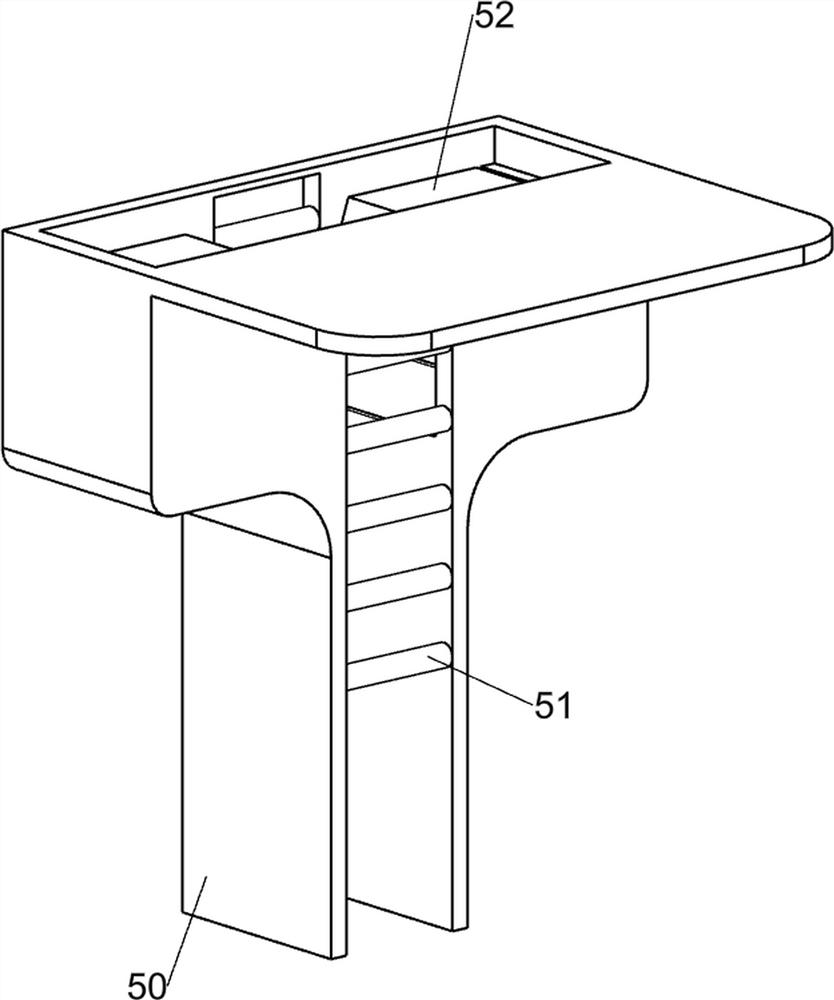
[0024] The shaping mechanism 5 includes a mounting frame 50, a roller 51 and a special-shaped block 52. The middle of the bottom plate 1 top is fixedly connected with the mounting frame 50. The left and right sides of the mounting frame 50 are evenly spaced and rotated to...

Embodiment 2

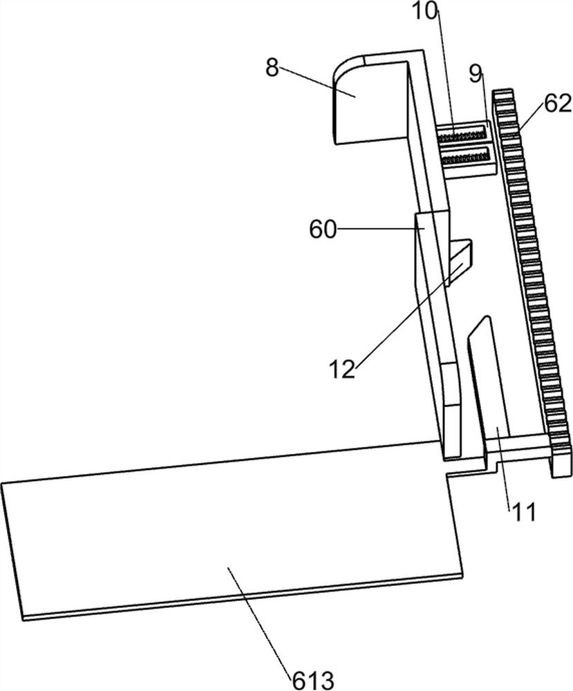
[0032] On the basis of Example 1, such as Figure 6 with Figure 7 As shown, it also includes a sliding plate 8, a limiting plate 9, a third spring 10, a first wedge block 11 and a second wedge block 12, and two limiting plates 9 are installed on the left rear side of the top of the mounting frame 50. The plates 9 are connected with a third spring 10, the front ends of the third springs 10 are connected with a slide plate 8, the slide plate 8 is slidably connected with the installation frame 50, and the left part of the feeding push plate 613 is fixedly connected with the first wedge block 11 The right side of the rear part of the sliding plate 8 is fixedly connected with a second wedge block 12 , and the first wedge block 11 cooperates with the second wedge block 12 .

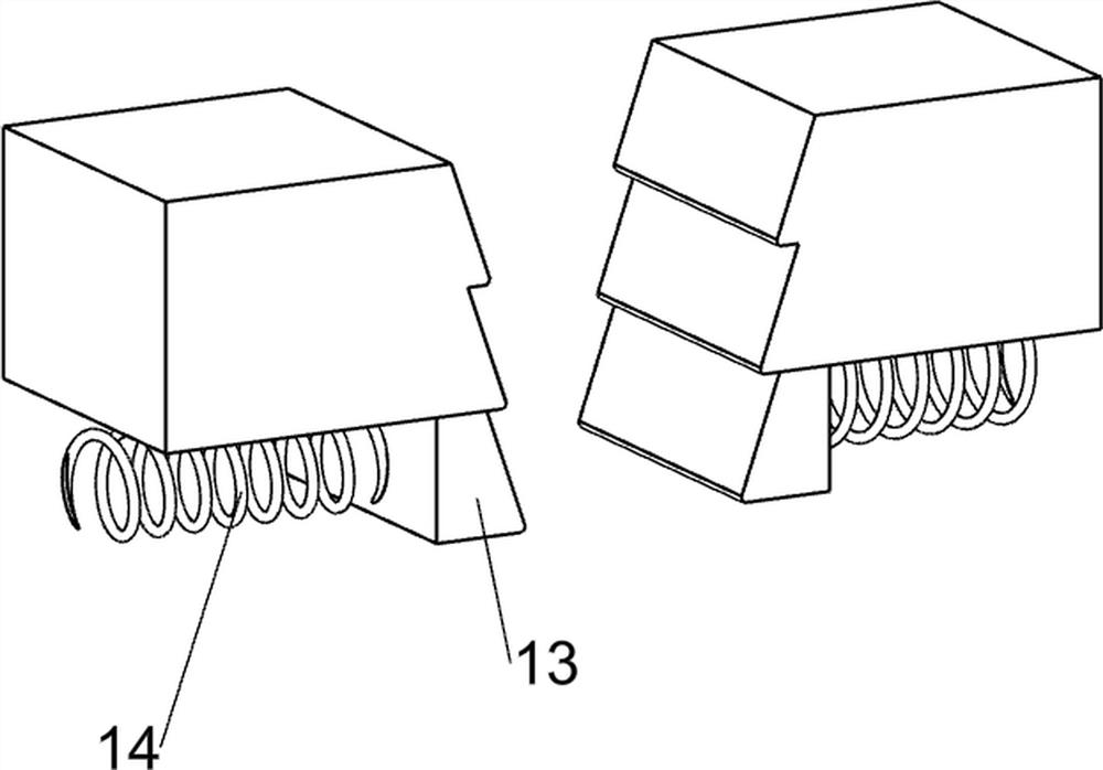
[0033] It also includes a third wedge block 13 and a fourth spring 14 , the third wedge block 13 is provided in the installation frame 50 in a front-back symmetrical sliding manner, and the fourth spring bloc...


PUM


Abstract

The invention relates to punching equipment, in particular to notched steel plate punching equipment for buildings. The notched steel plate punching equipment can push out a steel plate clamped on a punching block, can automatically feed the steel plate, and comprises a bottom plate, an air cylinder and the punching block, wherein the middle of the bottom plate is fixedly connected with an L-shaped rod; the air cylinder is installed on the L-shaped rod; and the punching block is connected to a piston rod of the air cylinder. According to the notched steel plate punching equipment, the effect that the steel plate clamped on the punching block can be pushed out and can be automatically fed is achieved, when the punching block moves downwards, a first rack and a feeding propelling plate can be driven to move leftwards through a series of transmissions, the lowermost steel plate can be pushed to the position below the punching block through leftward movement of the feeding propelling plate, then the feeding propelling plate is reset, and in this way, intermittent discharging is achieved.

Description

technical field [0001] The invention relates to a punching equipment, in particular to a punching equipment for a notch-shaped steel plate for construction. Background technique [0002] Steel plate is a flat steel material that is cast with molten steel and pressed after cooling. The steel plate has high strength, good corrosion resistance and high toughness. It is mainly used for building buildings, ships and bridges. [0003] After the steel plate is produced, it needs to be processed into various shapes and then installed in different machines. One of the notched steel plates is an indispensable material in the construction field. At present, people are punching notches When forming steel plates, people often manually place the steel plate raw materials in the stamping machine, and then stamp the steel plate through the stamping machine. However, this stamping method has certain shortcomings. After the steel plate is stamped, it is easier to get stuck on the stamping par...

Claims


Application Information

Patent Timeline
Patent Type & Authority Applications(China)
IPC IPC(8): B21D22/02B21D43/04
CPCB21D22/02B21D43/04
Inventor 李冰娜
Owner 李冰娜
Why Eureka
Try Eureka