
Compression devices, welding equipment and welding systems

A compression device and welding equipment technology, applied in welding equipment, auxiliary welding equipment, welding/cutting auxiliary equipment, etc., can solve the problems of wave deformation on the side of the thin plate, weld angle deformation, and difficult automatic welding, etc., to prevent welding Seam cracking, prevent corner deformation and misalignment, and ensure the effect of consistent appearance

Active Publication Date: 2022-03-15
ZOOMLION HEAVY IND CO LTD
View PDF22 Cites 0 Cited by
  • Summary
  • Abstract
  • Description
  • Claims
  • Application Information

AI Technical Summary

Problems solved by technology

Since the butt weld of the boom of the pump truck is a short weld, the design of the direction of the butt weld of the boom is not perpendicular to the length direction of the boom, and there is a difference in the thickness of the base metal on both sides of the butt weld, so the weld needs to be welded on one side and on both sides. Surface forming, the front and back reinforcement of the weld must be 0~1mm; so it is not easy to realize automatic welding
At present, manual welding is basically used in the industry, but manual manual welding will have the following problems: low efficiency; poor appearance and internal quality of the weld; there is a difference in thickness of the base metal on both sides of the weld, and the expansion value of the thin plate side is greater than that of the thick plate side during welding , the thin plate side is prone to wavy deformation, resulting in misalignment of the weld after welding; the base metal on both sides of the weld is not fixed and limited, and the weld corner deformation after welding is large, and a leveling process needs to be added after welding

Method used


Image

  • Compression devices, welding equipment and welding systems
  • Compression devices, welding equipment and welding systems
  • Compression devices, welding equipment and welding systems

Examples


Embodiment Construction

[0033] Specific embodiments of the present invention will be described in detail below in conjunction with the accompanying drawings. It should be understood that the specific embodiments described here are only used to illustrate and explain the present invention, and are not intended to limit the present invention.

[0034] In the present invention, unless stated otherwise, the used orientation words such as "upper and lower" are usually based on the orientation shown in the corresponding drawings.

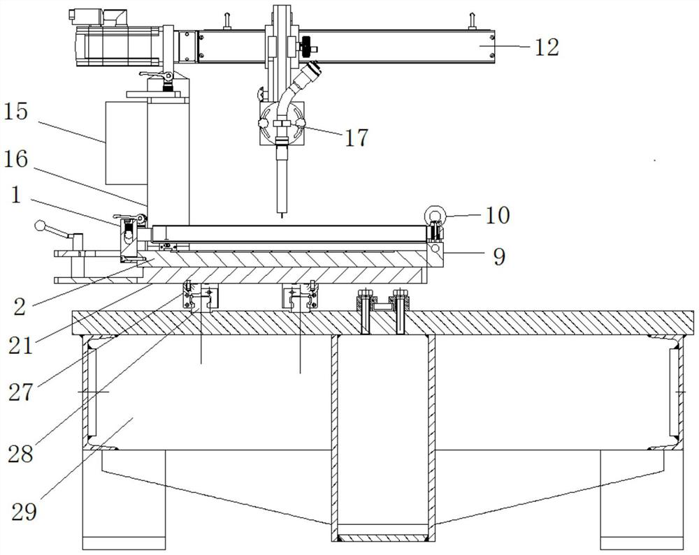
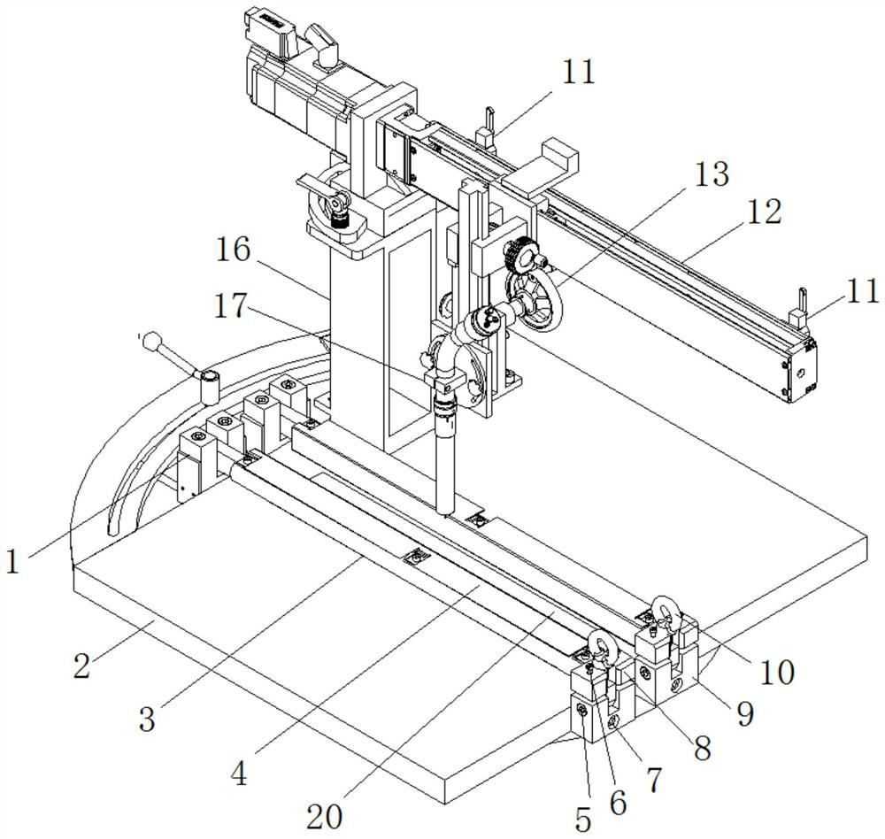
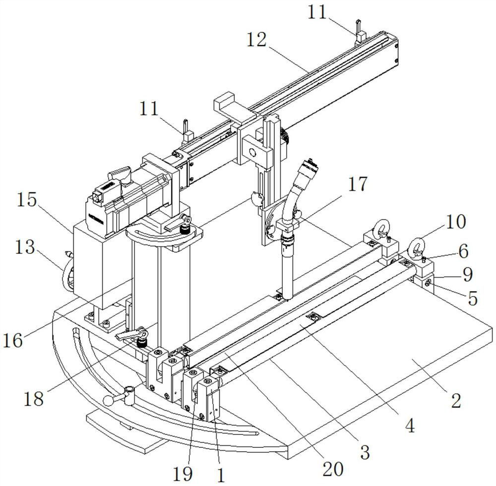
[0035] The first aspect of the present invention provides a pressing device, such as Figure 2-3 As shown, the pressing device includes a welding base 2 for placing workpieces and a pair of pressing shaft mechanisms arranged on the welding base 2 for pressing the two workpieces to be welded respectively. The pinch mechanism includes a pinch 3 and a mounting unit for mounting the pinch 3 on the welding base 2, the pinch 3 is rotatably mounted on the mounting unit so as to be abl...


PUM

PropertyMeasurementUnit
lengthaaaaaaaaaa
widthaaaaaaaaaa

Abstract

The invention relates to the field of welding technology, in particular to a pressing device, welding equipment and a welding system. Wherein, the pressing device includes a welding base (2) for placing workpieces and a pair of pressing shaft mechanisms arranged on the welding base (2) for respectively pressing the two workpieces to be welded , the finale mechanism includes a finale (3) and an installation unit for installing the finale (3) on the welding base (2), the finale (3) is rotatably installed on the installation unit, The workpiece can be rotated around the axis of the pressing shaft (3) when pressing the workpiece, so that the workpiece will not be hindered from shrinking toward the welding seam while pressing the workpiece. The pressing device, welding equipment and welding system can prevent corner deformation and edge misalignment after welding, will not hinder the workpiece from shrinking toward the weld, prevent weld cracking, and improve weld quality and welding efficiency.

Description

technical field [0001] The invention relates to the field of welding technology, in particular to a pressing device, welding equipment and a welding system. Background technique [0002] The pump truck is the most commonly used concrete pumping equipment in construction. In order to improve the performance of the pump truck and reduce fuel consumption, it is necessary to control the weight of the whole truck as much as possible. Therefore, on the basis of satisfying the force and strength of the pump truck, The web and cover weldments of high-strength steel structural parts such as booms and legs of pump trucks usually adopt the form of thick and thin plate butt joints. Generally, there are many pump truck product models and boom models, and the position and angle of the butt weld on the pump truck boom of each model are different. The length and width of the boom are different, and the length of the boom is about 4000mm ~ 10000mm , The width is about 150mm ~ 500mm. The we...

Claims


Application Information

Patent Timeline
Patent Type & Authority Patents(China)
IPC IPC(8): B23K37/04B23K37/00
CPCB23K37/0443B23K37/00
Inventor 彭和永蒋海刚
Owner ZOOMLION HEAVY IND CO LTD
Learn More