
Method and tool for drilling and marking of common machine tool

A machine tool and marking technology, applied in the field of signal plate processing, can solve problems such as processing difficulties, and achieve the effects of stable quality, high efficiency, fast and reliable clamping

Pending Publication Date: 2021-01-22
GUANGXI YUCHAI MASCH CO LTD
View PDF0 Cites 0 Cited by
  • Summary
  • Abstract
  • Description
  • Claims
  • Application Information

AI Technical Summary

Problems solved by technology

In some enterprises without high-priced CNC machining centers, it has caused processing difficulties, and it is necessary to find a way to arrange them to be processed on ordinary boring and milling machines.

Method used


Image

  • Method and tool for drilling and marking of common machine tool
  • Method and tool for drilling and marking of common machine tool
  • Method and tool for drilling and marking of common machine tool

Examples


Embodiment Construction

[0024] Below in conjunction with embodiment, the present invention is further described, but does not constitute any restriction to the present invention, anyone makes the limited number of amendments in the scope of claims of the present invention, still within the scope of claims of the present invention.

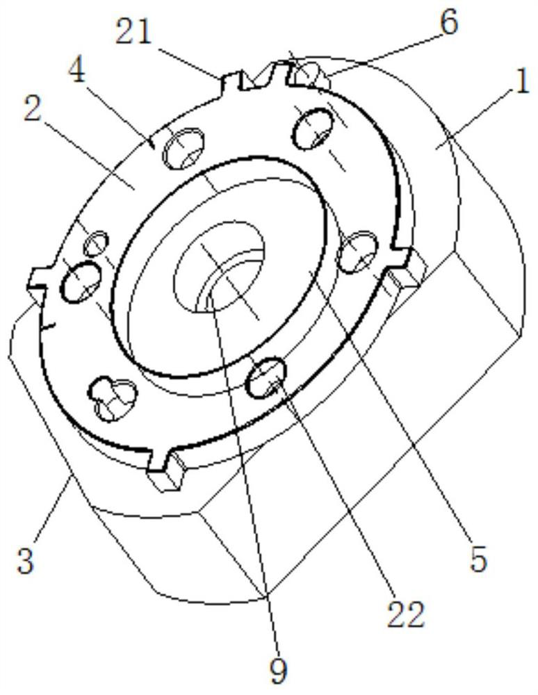
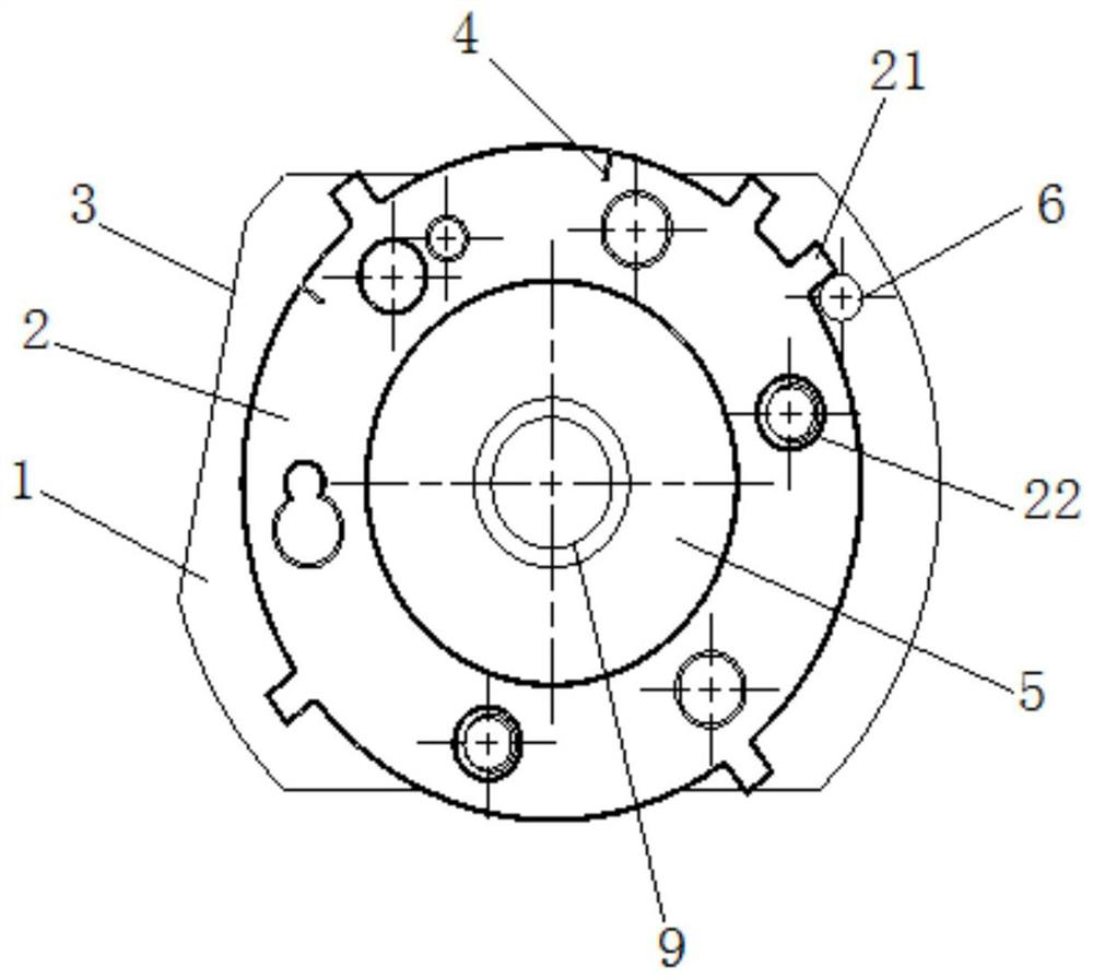
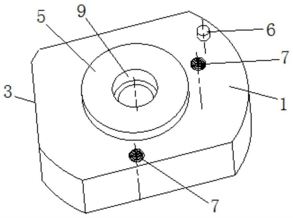
[0025] The specific embodiment of the present invention is like this: with reference to Figure 1-4 As shown, a method for drilling and marking markings on ordinary machine tools includes the following steps: setting a support base 1 on the machine tool table to support the signal plate 2, and setting a positioning structure on the support base 1 to support the signal plate 2. Position the disk 2; set the marking line tool alignment surface 3 at one end of the support base 1 and adjust the position of the support base 1 so that the marking line tool alignment surface 3 is parallel to the X-axis direction of the worktable, and the milling cutter is aligned with the marking ...


PUM


Abstract

The invention discloses a method for drilling and marking of a common machine tool. The method comprises the following steps that a supporting base is arranged on a machine tool workbench to support asignal panel, and a positioning structure is arranged on the supporting base to position the signal panel; and a marking tool setting face is arranged at one end of the supporting base, the positionof the supporting base is adjusted to enable the marking tool setting face to be parallel to an X-axis direction of the workbench, and during machining, a milling cutter and the marking tool setting face are subjected to tool setting, then the workbench is moved by a certain distance in a Y-axis direction, and finally the milling cutter machines a marking on the signal panel in the X-axis direction. The invention further discloses a tool for drilling and marking of the common machine tool. The method and tool for drilling and marking of the common machine tool belong to the technical field ofsignal panel machining, a through hole in the signal panel can be rapidly machined in a common boring and milling machine, the marking can be rapidly marked on the common boring and milling machine, workpieces do not need to be corrected one by one, machining in a three-axis numerical control machining center is not needed, the machining cost is low, and safety and high efficiency are achieved.

Description

technical field [0001] The present invention relates to signal disk processing technology, more specifically, it relates to a kind of tooling used for common machine tool drilling, scoring and marking lines. Background technique [0002] There is a batch of "timing signal plate" remanufactured parts. The workpiece needs to add 4 holes and a timing marking line on the basis of the original 4 holes. Under the existing technology, it is generally arranged to process at the CNC machining center. In some enterprises that do not have high-priced CNC machining centers, it has caused processing difficulties, and they must find a way to arrange processing on ordinary boring and milling machines. Contents of the invention [0003] The technical problem to be solved by the present invention is to address some of the above-mentioned deficiencies in the prior art. One of the objectives of the present invention is to provide a method for drilling and marking markings for ordinary machi...

Claims


Application Information

Patent Timeline
Patent Type & Authority Applications(China)
IPC IPC(8): B23P23/04B23Q3/06B23Q15/22B23Q17/22
CPCB23P23/04B23Q15/22B23Q17/22B23Q3/06
Inventor 陈雪冲肖晓路
Owner GUANGXI YUCHAI MASCH CO LTD
Learn More