
Detection tool structure for floor rear lower crossbeam

A technology for detecting tooling and beams, which is applied in the field of tooling structure detection of the lower beam behind the floor, can solve the problems of high labor intensity and other problems, and achieve the effect of providing convenience, facilitating all-round detection and stable positioning.

Inactive Publication Date: 2021-01-22
十堰澳士力工贸有限公司
View PDF0 Cites 2 Cited by
  • Summary
  • Abstract
  • Description
  • Claims
  • Application Information

AI Technical Summary

Problems solved by technology

[0002] When the existing car floor rear crossbeam is inspected, it needs to be manually fixed, and at the same time, the crossbeam needs to be turned over for multi-directional inspection, and at the same time, different positions are adjusted for detection. The detection components are all manually adjusted by adjusting the position of the crossbeam. In this way The manual labor intensity of the detection is high, therefore, a floor rear lower beam detection tooling structure is needed to solve the above problems

Method used


Image

  • Detection tool structure for floor rear lower crossbeam
  • Detection tool structure for floor rear lower crossbeam
  • Detection tool structure for floor rear lower crossbeam

Examples


Embodiment Construction

[0018] The present invention will be further described below in conjunction with the examples.

[0019] The following examples are used to illustrate the present invention, but cannot be used to limit the protection scope of the present invention. The conditions in the embodiment can be further adjusted according to the specific conditions, and the simple improvement of the method of the present invention under the premise of the concept of the present invention belongs to the protection scope of the present invention.

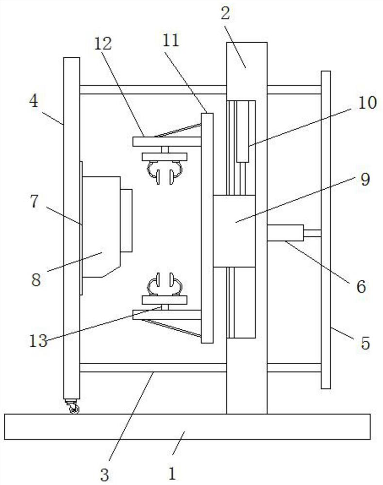
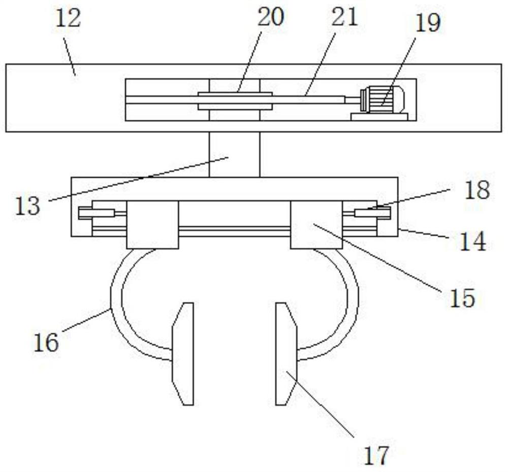
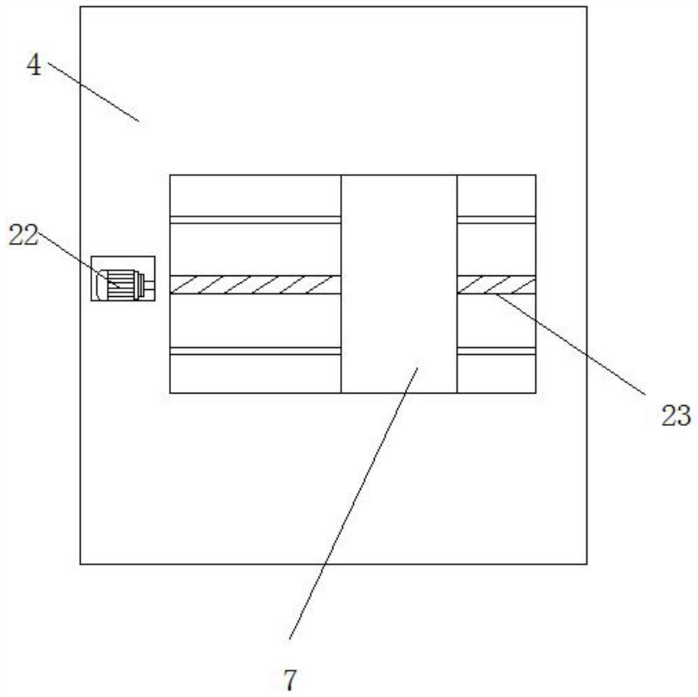
[0020] see Figure 1-3 , the present invention provides a floor rear lower beam detection tooling structure, including a base plate 1, a riser 2 is fixedly installed on the top of the base plate 1, a lifting block 9 is slidably installed on one side of the riser 2, and a lifting block 9 is fixedly installed on one side There is a lifting plate 11, and one side of the lifting plate 11 is fixedly equipped with two horizontal plates 12, and the opposite side of ...


PUM


Abstract

The invention discloses a detection tool structure for a floor rear lower crossbeam, and belongs to the technical field of crossbeam detection. The detection tool structure comprises a bottom plate, avertical plate is fixedly mounted at the top of the bottom plate, a lifting block is slidably mounted on one side of the vertical plate, a lifting plate is fixedly mounted on one side of the liftingblock, two transverse plates are fixedly mounted on one side of the lifting plate, rotating shafts are rotationally installed on the opposite sides of the two transverse plates, a positioning table isfixedly installed at one end of each rotating shaft, two movable blocks are installed on the side, away from the corresponding rotating shaft, of each positioning table in a sliding mode, clamping rods are fixed to the movable blocks, clamping blocks are fixed to one ends of the clamping rods, and a vertically-arranged track plate is installed on the bottom plate in a sliding mode. According to the detection tool structure for the floor rear lower crossbeam, fixation and electric fixation of the crossbeam are realized, the positioning is stable, then the detection is facilitated, meanwhile, the adjustment on the spatial positions of a detection assembly and the crossbeam is realized, through cooperation with rotation adjustment of the crossbeam, the omnibearing detection of the crossbeamis facilitated, and great convenience is provided.

Description

technical field [0001] The invention belongs to the technical field of beam detection, and in particular relates to a tooling structure for detecting a lower beam behind a floor. Background technique [0002] When the existing car floor rear crossbeam is inspected, it needs to be manually fixed, and at the same time, the crossbeam needs to be turned over for multi-directional inspection, and at the same time, different positions are adjusted for detection. The detection components are all manually adjusted by adjusting the position of the crossbeam. In this way The manual labor intensity of the detection is high, therefore, a kind of tooling structure for detecting the lower cross beam behind the floor is needed to solve the above problems. Contents of the invention [0003] The object of the present invention is to provide a floor rear lower beam detection tooling structure to solve the problems raised in the above-mentioned background technology. [0004] In order to ac...

Claims


Application Information

Patent Timeline
Patent Type & Authority Applications(China)
IPC IPC(8): B25H1/02B25H1/10B25H1/16
CPCB25H1/02B25H1/10B25H1/16
Inventor 陈莹卢平官建清范建莉张静
Owner 十堰澳士力工贸有限公司
Learn More