
Quick-change device capable of automatically conducting hydraulic and electrical channels

A hydraulic and conduction technology, applied in the direction of fluid pressure actuation device, mechanically driven excavator/dredger, earth mover/shovel, etc. The effect of efficient operation, simple structure and low cost

Inactive Publication Date: 2021-01-22
安徽恒创智能装备有限公司
View PDF3 Cites 2 Cited by
  • Summary
  • Abstract
  • Description
  • Claims
  • Application Information

AI Technical Summary

Problems solved by technology

In order to meet the different work needs of users, different types of work attachments need to be replaced frequently during construction, such as some hydraulic hammers, hydraulic grabs, hydraulic rammers, hydraulic shears, hydraulic saws, etc. To connect oil circuits and control signals, etc., it is usually achieved by driving the equipment into a safe area, using hydraulic quick change and manual loading and unloading of oil pipes and circuits, which is time-consuming and laborious. In some environments such as underwater and nuclear radiation, relying on human Going to the scene to change equipment, this kind of operation method is almost difficult to realize, and it is very easy to cause accidents such as personal injury

Method used


Image

  • Quick-change device capable of automatically conducting hydraulic and electrical channels
  • Quick-change device capable of automatically conducting hydraulic and electrical channels
  • Quick-change device capable of automatically conducting hydraulic and electrical channels

Examples


Embodiment Construction

[0020] In order to make the above objects, features and advantages of the present invention more comprehensible, specific implementations of the present invention will be described in detail below in conjunction with the accompanying drawings. In the following description, numerous specific details are set forth in order to provide a thorough understanding of the present invention. However, the present invention can be implemented in many other ways different from those described here, and those skilled in the art can make similar improvements without departing from the connotation of the present invention, so the present invention is not limited by the specific implementations disclosed below.

[0021] It should be noted that when an element is referred to as being “fixed” to another element, it can be directly on the other element or there can also be an intervening element. When an element is referred to as being "connected to" another element, it can be directly connected ...


PUM


Abstract

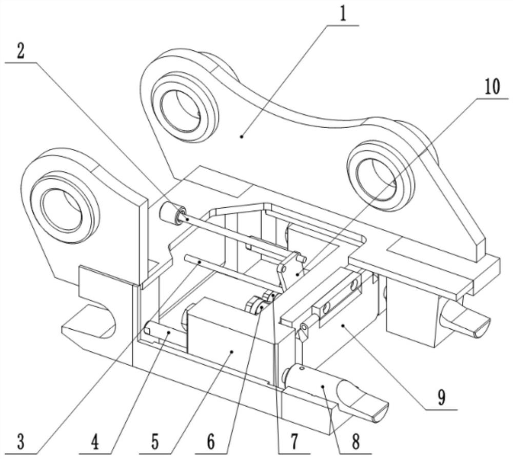
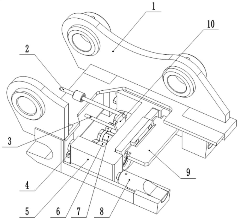
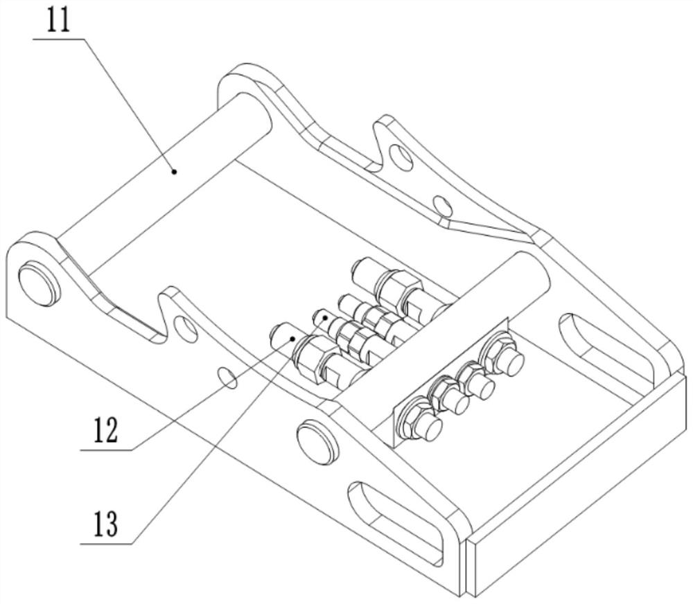
The invention discloses a quick-change device capable of automatically conducting hydraulic and electrical channels. The quick-change device comprises an upper connecting frame and a lower connectingframe. The upper connecting frame comprises a machine frame, a signal rod, a supporting rod, hydraulic push rods, a valve body, hydraulic quick-plug female ends, electrical quick-plug female ends, spring bolts, a fender and a bracket. The lower connecting frame comprises a lower machine frame, hydraulic quick-plug male ends and electrical quick-plug male ends, the hydraulic push rods are installedin the valve body, and the telescopic ends of the hydraulic push rods are fixed to the machine frame; and the hydraulic quick-plug female ends, the electrical quick-plug female ends and the spring bolts are fixed to the valve body. By operating the quick-change device, the purpose of easily and quickly replacing different working accessories can be achieved; and meanwhile, automatic conducting ofa hydraulic oil way and a control circuit between a main machine and the lower connecting working accessory is achieved, and the quick-change device is particularly important to be applied to some high-risk environments and special working conditions.

Description

technical field [0001] The invention relates to the technical field of engineering machinery, in particular to a quick-change device used in conjunction with hydraulic excavators, engineering robots and other hosts to replace different work attachments. Background technique [0002] With the development of society, people increasingly hope to use robots to replace themselves to complete those boring, heavy and dangerous tasks, such as slag breaking, stripping and cleaning of brick kilns and smelting furnaces in cement, steel and other industrial industries. In special working conditions such as dismantling, handling, sorting, shipping, and some underwater conditions in nuclear energy facilities with strong radiation and chemical industries involving highly toxic liquids and gases, engineering robots and some After the transformation, hydraulic excavators and other equipment are used for operations. In order to meet the different work needs of users, different types of work ...

Claims


Application Information

Patent Timeline
Patent Type & Authority Applications(China)
IPC IPC(8): E02F3/36F15B13/02
CPCE02F3/3609F15B13/02E02F3/3654
Inventor 黄志远徐必勇赵玄烨吕玉虎潘国平郭威
Owner 安徽恒创智能装备有限公司
Learn More