
Waste heat recovery equipment and waste heat recovery method for thermal power plant

A technology for waste heat recovery equipment and thermal power plants, applied in the field of waste heat recovery, can solve problems affecting heat exchange efficiency, adjustment of stirring speed, insufficient waste heat recovery, etc., and achieve the effect of increasing heat exchange efficiency and changing stirring speed

Active Publication Date: 2022-05-24
德昂智控(南京)科技有限公司
View PDF0 Cites 0 Cited by
  • Summary
  • Abstract
  • Description
  • Claims
  • Application Information

AI Technical Summary

Problems solved by technology

[0003] At present, the waste heat recovery equipment in the prior art cannot mix and stir the slag, causing the slag to stick together, and most waste heat recovery equipment cannot adjust the stirring speed according to the amount of slag, which will cause the slag to dissipate heat The effect is not ideal, which affects the heat exchange efficiency, which leads to the problem of insufficient waste heat recovery

Method used


Image

  • Waste heat recovery equipment and waste heat recovery method for thermal power plant
  • Waste heat recovery equipment and waste heat recovery method for thermal power plant
  • Waste heat recovery equipment and waste heat recovery method for thermal power plant

Examples


Embodiment 1

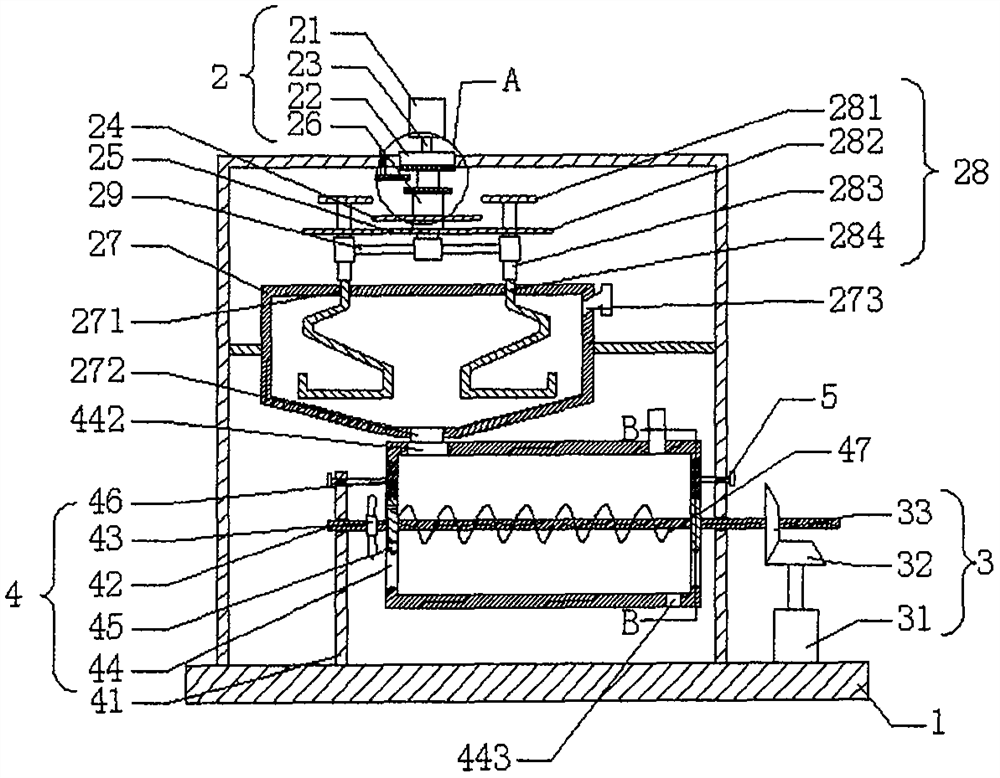
[0030] see Figure 1-4 , the waste heat recovery equipment for thermal power plants provided by the embodiment of the present invention includes a bottom plate 1, a stirring mechanism 2, a driving mechanism 3, a recovery mechanism 4 and a clamping mechanism 5, and the recovery mechanism 4 is rotatably arranged on the Above the bottom plate 1 , the driving mechanism 3 is fixedly arranged on the upper end of the bottom plate 1 , the clamping mechanism 5 is fixedly arranged on both sides of the recovery mechanism 4 , and the stirring mechanism 2 is rotatably arranged on the recovery mechanism 4 above;

[0031]The stirring mechanism 2 includes a drive motor 21, a fixed block 22, a center rod 23, a first gear 24, a second gear 25, a sliding sleeve 26, a collection funnel 27 and a stirring assembly 28. The two ends of the fixed block 22 pass through. The bracket is fixedly installed on the bottom plate 1, the driving motor 21 is fixedly arranged on the upper end of the fixing block...

Embodiment 2

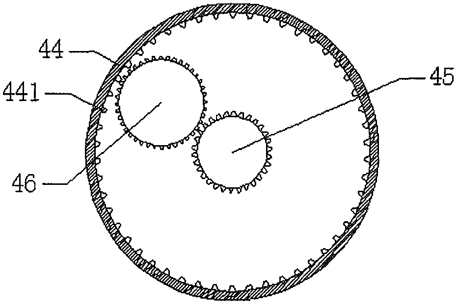
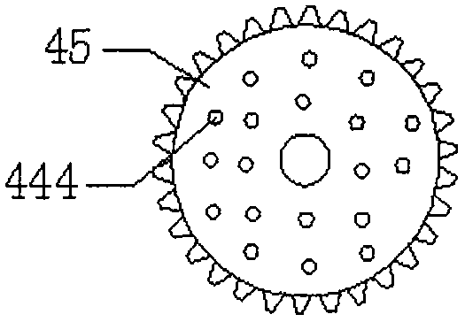
[0036] In the first embodiment, there is still a problem that the waste heat of the slag cannot be recovered and utilized. Therefore, on the basis of the first embodiment, this embodiment further includes: the recovery mechanism 4 includes two support rods 41, a rotating rod 42, a refrigeration The fan 43 , the rotating casing 44 , the fifth gear 45 , the sixth gear 46 and the auger 47 , the bottom ends of the two supporting rods 41 are fixedly installed on the upper end of the base plate 1 , and the rotating rod 42 is rotatable. The two supporting rods 41 are arranged on the two supporting rods 41, the rotating rod 42 passes through the two supporting rods 41, the rotating casing 44 is fixedly arranged on the rotating rod 42, and the rotating casing 44 is arranged horizontally. Both ends of the rotating housing 44 in the horizontal direction are provided with movable cavities, the two fifth gears 45 are fixedly arranged on the rotating rod 42 , and the two fifth gears 45 are l...

Embodiment 3

[0041] see figure 1 , in this embodiment, the present invention also proposes a waste heat recovery method for the waste heat recovery equipment of a thermal power plant, comprising the following steps:

[0042] Step 1, put the slag used by the thermal power plant into the collecting funnel 27 from the feeding port 273, start the driving motor 21, the driving motor 21 will drive the center rod 23 to rotate, and the center rod 23 will drive the second rod during the rotation process. The rotation of the gear 25 drives the fourth gear 282 to rotate, and drives the third connecting rod 283 to rotate, thereby driving the stirring rod 284 to rotate, thereby mixing and stirring the slag;

[0043] Step 2, when the stirring speed needs to be adjusted, the second connecting rod 210 is rotated, so that the third magnet 222 will leave the original position. Due to the action of the magnetic force, the first magnet 261 and the second magnet 221 will The sliding sleeve 26 drives the upwar...


PUM


Abstract

The invention discloses waste heat recovery equipment for a thermal power plant, comprising a bottom plate, a stirring mechanism, a driving mechanism, a recovery mechanism and a clamping mechanism, the recovery mechanism is rotatably arranged above the bottom plate, and the driving mechanism is fixedly arranged On the top of the bottom plate, the clamping mechanism is fixedly arranged on both sides of the recovery mechanism, and the stirring mechanism is rotatably arranged above the recovery mechanism; the invention also discloses waste heat recovery equipment for thermal power plants waste heat recovery method. The beneficial effects of the present invention are: the center rod designed by the present invention will drive the second gear to rotate during the rotation process, thereby driving the fourth gear to rotate, further, it can drive the stirring rod to rotate, and then can mix and stir the slag, When the second connecting rod is rotated, the third magnet can be separated from the first magnet and the second magnet, so that the first magnet and the second magnet attract each other, and the sliding sleeve is driven upward, so that the first gear and the second magnet are attracted together. The third gear meshes, so that the effect of changing the stirring speed can be achieved, and the heat exchange efficiency of the slag can be increased.

Description

technical field [0001] The invention belongs to the technical field of waste heat recovery, and in particular relates to waste heat recovery equipment used in thermal power plants. Background technique [0002] Waste heat refers to the sensible heat and latent heat that have not been reasonably utilized in the original design of the energy-consuming devices of industrial enterprises that have been put into operation due to the limitations of history, technology, concepts and other factors. It includes waste heat of high-temperature exhaust gas, waste heat of cooling medium, waste heat of waste steam and waste water, waste heat of high-temperature products and slag, waste heat of chemical reaction, waste heat of combustible waste gas and waste liquid and waste heat, etc. According to the survey, the total waste heat resources of various industries account for about 17% to 67% of their total fuel consumption, and the recyclable waste heat resources are about 60% of the total w...

Claims


Application Information

Patent Timeline
Patent Type & Authority Patents(China)
IPC IPC(8): F27D17/00F28D21/00
CPCF27D17/004F28D21/0001Y02P10/25
Inventor 不公告发明人
Owner 德昂智控(南京)科技有限公司
Learn More