A permanent magnet synchronous motor rotor assembly for vehicles, its design method and motor

A permanent magnet synchronous motor and rotor technology, applied in the direction of magnetic circuit rotating parts, magnetic circuits, electromechanical devices, etc., can solve the problems of easy falling off of balance mud, unreliable connection, torque attenuation, etc., to reduce product weight and cost, The effect of eliminating the dynamic balance plate and shortening the axial length

Active Publication Date: 2022-04-15
CHINA FIRST AUTOMOBILE
View PDF0 Cites 0 Cited by
  • Summary
  • Abstract
  • Description
  • Claims
  • Application Information

AI Technical Summary

Problems solved by technology

If the dynamic balance accuracy of the motor is low, vibration noise will be generated, which will cause coercive excitation to the support bearing and reduce the service life of the motor, especially for vehicle drive motors, which have higher requirements on NVH and reliability, so their dynamic balance accuracy level requirements are also higher
[0003] The traditional permanent magnet synchronous motor rotor assembly mainly includes iron core with magnetic steel assembly, rotor shaft, dynamic balance end plate, etc., in which the dynamic balance accuracy level of the rotor assembly is achieved by removing weight on the dynamic balance plate, and the balance plate generally chooses Steel, aluminum, and some copper materials can be used as the basic material, which can play a certain role in magnetic isolation and fixed permanent magnets, but this solution will inevitably increase the axial length and increase the cost and weight of rotor assembly components
At the same time, traditional weight-increasing methods such as bonding balance mud, the balance mud is easy to fall off under high-speed and harsh impact conditions, welding nuts are prone to welding stress, and threaded connection counterweight methods have attenuation of torque and are prone to unreliable connections. Happening

Method used


Image

  • A permanent magnet synchronous motor rotor assembly for vehicles, its design method and motor
  • A permanent magnet synchronous motor rotor assembly for vehicles, its design method and motor
  • A permanent magnet synchronous motor rotor assembly for vehicles, its design method and motor

Examples


Embodiment Construction

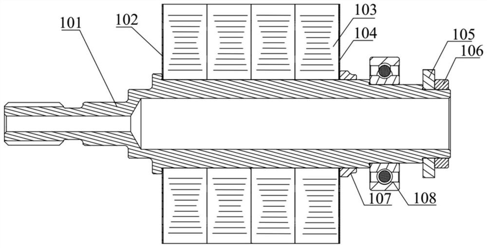
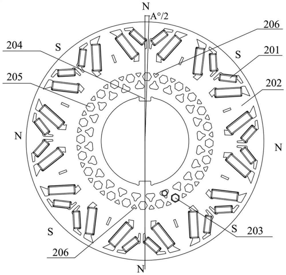
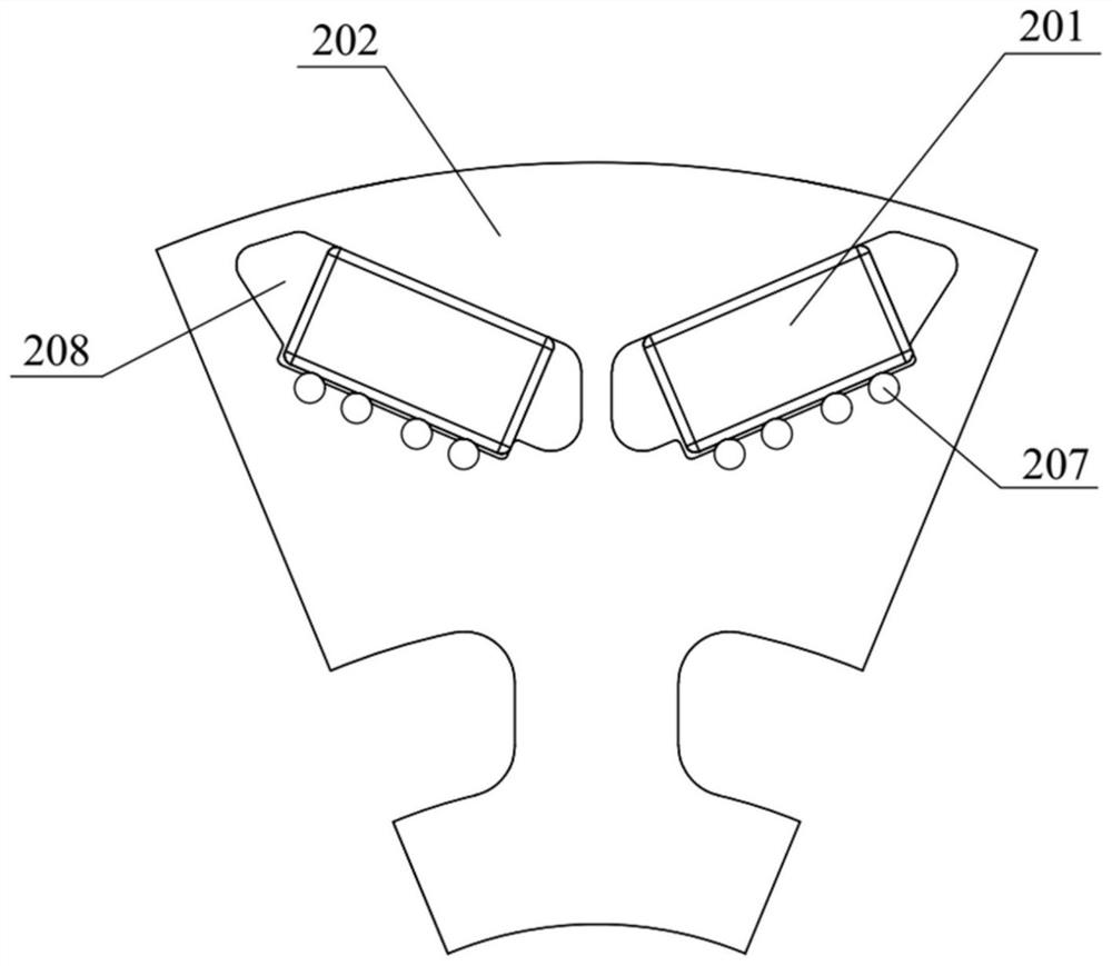
[0051] In order to enable those skilled in the art to better understand the technical solution of the present invention, the technical solution of the present invention will be further described below in conjunction with the accompanying drawings and through specific implementation methods.

[0052]In the description of the present invention, unless otherwise clearly specified and limited, the terms "connected", "connected" and "fixed" should be understood in a broad sense, for example, it can be a fixed connection, a detachable connection, or an integrated ; It can be a mechanical connection or an electrical connection; it can be a direct connection or an indirect connection through an intermediary, and it can be the internal communication of two components or the interaction relationship between two components. Those of ordinary skill in the art can understand the specific meanings of the above terms in the present invention in specific situations.

[0053] In the present in...


PUM


Abstract

The invention relates to the technical field of permanent magnet synchronous motors, in particular to a permanent magnet synchronous motor rotor assembly for vehicles, a design method thereof and a motor. The rotor assembly of the permanent magnet synchronous motor for vehicles provided by the present invention includes a rotor shaft, a rotor iron core magnetic steel assembly and a magnetic isolation fixed end plate, and the rotor iron core magnetic steel assembly includes a permanent magnet, a rotor iron core and a counterweight pin , the rotor core is connected with the rotor shaft key, the rotor core is provided with a permanent magnet slot and a weight removal hole, the permanent magnet is inserted into the permanent magnet slot, and the counterweight pin is inserted into the weight removal hole; the magnetic isolation fixed end plate It is connected with the rotor shaft key, and two magnetically isolated fixed end plates are respectively arranged at both ends of the rotor iron core attached magnetic steel assembly. The rotor assembly of the permanent magnet synchronous motor for vehicles can save the dynamic balance plate by arranging the counterweight pin in the weight removal hole of the rotor iron core, and at the same time reduce the weight of the magnetic isolation fixed end plate and reduce the The thickness of the magnetically fixed end plate shortens the axial length of the rotor assembly and reduces product weight and cost.

Description

technical field [0001] The invention relates to the technical field of permanent magnet synchronous motors, in particular to a permanent magnet synchronous motor rotor assembly for vehicles, a design method thereof and a motor. Background technique [0002] With the development of new energy vehicles, the electric drive system is developing towards high voltage, high speed, and miniaturization, so its structure is more compact and its cost requirements are higher. If the dynamic balance accuracy of the motor is low, vibration noise will be generated, which will cause coercive excitation to the support bearing and reduce the service life of the motor, especially for vehicle drive motors, which have higher requirements on NVH and reliability, so their dynamic balance accuracy level requirements are also higher . [0003] The traditional permanent magnet synchronous motor rotor assembly mainly includes iron core with magnetic steel assembly, rotor shaft, dynamic balance end pl...

Claims


Application Information

Patent Timeline
Patent Type & Authority Patents(China)
IPC IPC(8): H02K1/274H02K1/28H02K7/04
CPCH02K1/274H02K1/28H02K7/04
Inventor 李全赵慧超徐德才苍衍林展汐胡波侯毅鹏齐红阳
Owner CHINA FIRST AUTOMOBILE
Why Eureka
Try Eureka