Solar charging device for bus station, and using method thereof

A charging device, bus station technology, applied in solar thermal power generation, circuit devices, solar thermal energy and other directions, can solve the problems of inability to adjust, prone to leakage, easy to enter water, etc., to facilitate charging work, improve stability, and enhance magnetic field. the effect of strength

Inactive Publication Date: 2021-01-22
安徽引航人广告标识有限公司
View PDF4 Cites 0 Cited by
  • Summary
  • Abstract
  • Description
  • Claims
  • Application Information

AI Technical Summary

Problems solved by technology

[0004] The object of the present invention is to provide a solar charging device for a bus stop and its use method, to solve the problem that the existing charging device for a bus stop cannot use solar energy, and it is necessary to lay wires and install plug-in boards, which are exposed to The outer side is prone to short-circuit caused by water ingress in rainy days, and at the same time, it is prone to leakage problems, threatening the personal safety of passengers; the existing solar charging device needs to use a plug-in board when charging, and different types of mobile phones need to provide different types of chargers. Charging is troublesome, and it is impossible to charge without carrying a charger when going out, which cannot solve practical problems. At the same time, from the wireless charging device, the position of the charging board cannot be changed, which is inconvenient to use, and the position between the magnetic fields of the two magnetic field coils cannot be adjusted, making charging The problem of inefficiency

Method used


Image

  • Solar charging device for bus station, and using method thereof
  • Solar charging device for bus station, and using method thereof
  • Solar charging device for bus station, and using method thereof

Examples


Embodiment Construction

[0029] The technical solutions of the present invention will be clearly and completely described below in conjunction with the embodiments. Apparently, the described embodiments are only some of the embodiments of the present invention, not all of them. Based on the embodiments of the present invention, all other embodiments obtained by persons of ordinary skill in the art without creative efforts fall within the protection scope of the present invention.

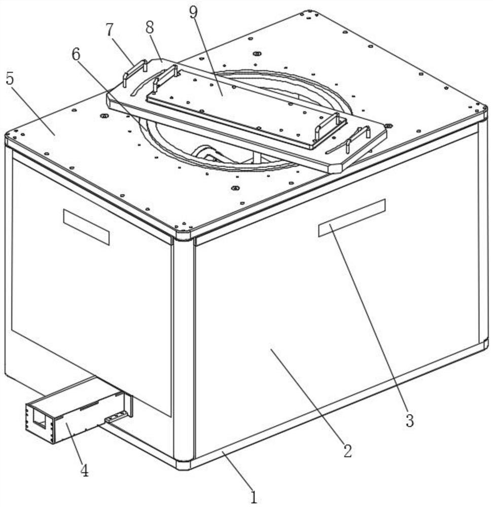
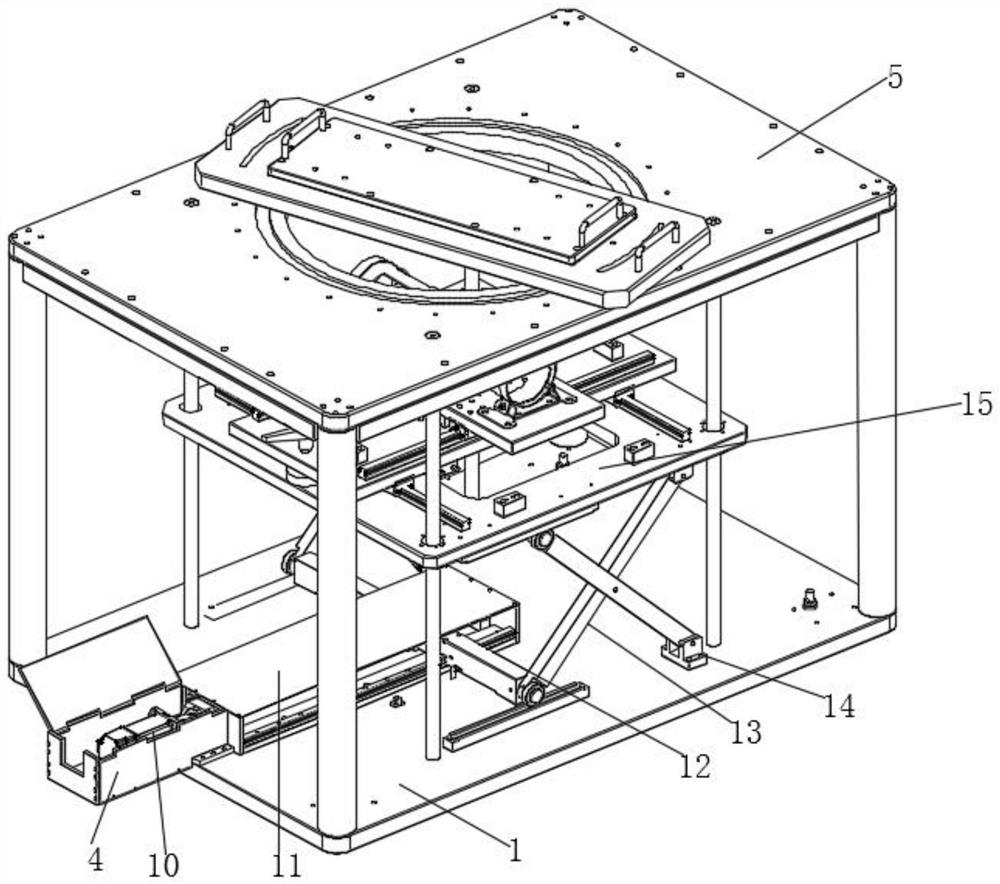
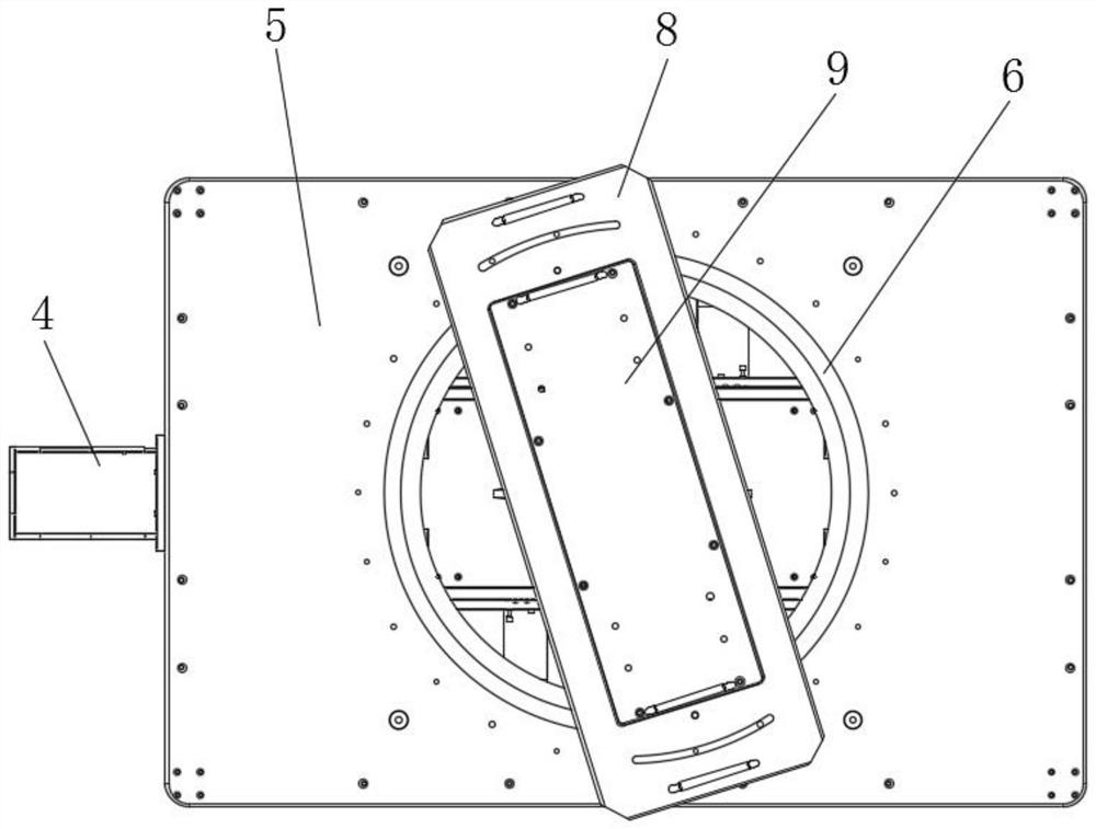
[0030] Such as Figure 1-5As shown, a solar charging device for a bus stop includes an underframe 1 and a top plate 5, the top of the underframe 1 is provided with a top plate 5, the middle position of the top plate 5 is provided with a circular track 6, and the circular track 6 is provided with a There is a rectangular plate 8, the top of the rectangular plate 8 is fixed with a charging plate 9, and the four side walls of the chassis 1 are equipped with photovoltaic panels 2, and the bottom end of each photovoltaic panel 2...


PUM


Abstract

The invention discloses a solar charging device for a bus station. The device comprises a bottom frame and a top plate, wherein the top plate is arranged at the top of the bottom frame, an annular rail is arranged in the middle of the top plate, and a rectangular plate is arranged on the annular rail. According to the invention, a first moving plate is pushed to move along two first sliding railsso as to achieve the longitudinal adjustment of a second moving plate, a rotating rod of a limiting mechanism is rotated to enable a screw rod to rotate, the first moving plate is fixed through a fixing block, the second moving plate is pushed to move along two second sliding rails so as to achieve transverse adjustment, after a magnetic field coil on the second moving plate is adjusted to a designated position, a built-in coil in a mobile phone induces the change of the magnetic field to generate induction current so as to achieve the wireless charging function of the mobile phone, and the charging efficiency is improved by adjusting the position of the magnetic field coil on the second moving plate, so that the problem that a traditional plugboard is exposed to the outer side, water easily enters the plugboard in rainy days, and a short circuit phenomenon is caused is solved.

Description

technical field [0001] The invention relates to the field of charging equipment for bus stops, in particular to a solar charging device for bus stops and a method for using the same. Background technique [0002] In daily work and life, it is simple and convenient to go out and take the bus. When the mobile phone is out of power, it cannot be charged on the bus platform. [0003] Existing charging devices for bus stops cannot use solar energy. It is necessary to lay wires and install plug-in boards. The plug-in boards are exposed to the outside and are prone to water ingress in rainy days, causing short circuits. At the same time, leakage problems are prone to occur, threatening the personal safety of passengers. ; The existing solar charging device needs to use a plug-in board when charging, and different types of mobile phones need to provide different types of chargers, which is troublesome to charge, and cannot be charged without carrying a charger when going out, which ...

Claims


Application Information

Patent Timeline
Patent Type & Authority Applications(China)
IPC IPC(8): H02S20/30H02S10/40H02J50/10F24S25/00
CPCF24S25/00F24S2025/012H02S10/40H02S20/30H02J50/10Y02E10/47Y02E10/50
Inventor 郭鹏
Owner 安徽引航人广告标识有限公司
Why Eureka
Try Eureka