Hop-by-hop monitoring system and method for implantable cardiac pacemaker

A cardiac pacemaker and monitoring system technology, applied in cardiac stimulators, electrotherapy, treatment, etc., can solve the problems of inaccurate and reasonable output of ventricular pulse energy, excitation interference of fusion wave algorithm, low accuracy, etc., to achieve Simplify the hop-by-hop monitoring method, reduce the number of issuances, and avoid the effect of extension or reduction

Pending Publication Date: 2021-01-26
SHAANXI QINMING MEDICAL CO LTD
View PDF0 Cites 2 Cited by
  • Summary
  • Abstract
  • Description
  • Claims
  • Application Information

AI Technical Summary

Problems solved by technology

[0005] This application provides a beat-by-beat monitoring system and method for implantable cardiac pacemakers to solve the problem of the relatively low accuracy of the beat-by-beat monitoring method for ventricu

Method used


Image

  • Hop-by-hop monitoring system and method for implantable cardiac pacemaker
  • Hop-by-hop monitoring system and method for implantable cardiac pacemaker
  • Hop-by-hop monitoring system and method for implantable cardiac pacemaker

Examples


Embodiment Construction

[0060] The embodiments will be described in detail hereinafter, examples of which are illustrated in the accompanying drawings. When the following description refers to the accompanying drawings, the same numerals in different drawings refer to the same or similar elements unless otherwise indicated. The implementations described in the following examples do not represent all implementations consistent with this application. These are merely examples of systems and methods consistent with aspects of the present application as recited in the claims.

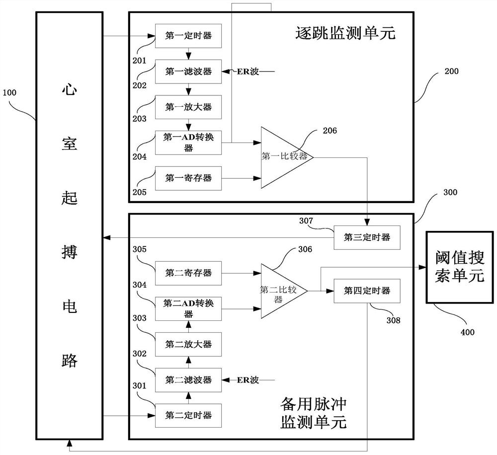
[0061] see figure 1 , which is a structural schematic diagram of a beat-by-beat monitoring system for an implantable cardiac pacemaker in this application.

[0062] The abbreviations in this application text are explained as follows:

[0063] As: atrial sensing;

[0064] Ap: atrial pacing pulse;

[0065] Vs: Ventricular sensing, an autoventricular activation of AV conduction;

[0066] PVC: premature ventricular contraction, ...


PUM


Abstract

The invention discloses a hop-by-hop monitoring system and method for an implantable cardiac pacemaker. A ventricular pacing circuit unit is electrically connected with a hop-by-hop monitoring unit; the hop-by-hop monitoring unit is electrically connected with a standby pulse monitoring unit and used for collecting ER waves generated by Vp and judging and outputting the capture/capture loss stateof the Vp; the standby pulse monitoring unit is electrically connected with the ventricular pacing circuit unit and used for triggering the ventricular pacing circuit unit to send out ventricular standby pulses Vp(B) after sending out ventricular pacing pulses Vp when the ER waves of the Vp are in the capture loss state, collecting ER waves of the Vp(B), judging and outputting the capture/ captureloss state of the Vp(B) and prolonging the AV interval when the Vp(B) is in the capture loss state; and a ventricular threshold value searching unit is electrically connected with the standby pulse monitoring unit and used for triggering the ventricular threshold value searching unit when the Vp(B) is in the capture loss state to obtain a ventricular pacing threshold value and reset ventricular pacing output.

Description

technical field [0001] The present application relates to the technical field of cardiac pacemakers, in particular to a beat-by-beat monitoring system and method for implantable cardiac pacemakers. Background technique [0002] The purpose of the ventricular pacing beat-by-beat monitoring function of an implantable cardiac pacemaker is to obtain the ER wave (that is, the depolarization wave) generated by each ventricular pacing pulse Vp, and determine whether Vp has captured the ventricle through the ER wave. When the determination result of beat-by-beat monitoring is capture, the pacemaker maintains the normal working state; when the determination result of beat-by-beat monitoring is loss of capture, the pacemaker immediately sends out the ventricular backup pulse Vp(B) and starts the ventricular Threshold search to obtain the current ventricular pacing threshold, so as to set a reasonable ventricular pacing output energy according to the obtained threshold, that is, a vent...

Claims


Application Information

Patent Timeline
IPC IPC(8): A61N1/362A61N1/37
CPCA61N1/362A61N1/3706A61N1/3708A61N1/3712A61N1/3714
Inventor 金华任江波陈小龙朱妙娜郝云龙张鸿
Owner SHAANXI QINMING MEDICAL CO LTD
Why Eureka
Try Eureka