
Variable-diameter coating stirring and mixing device for building

A stirring and mixing technology for construction, which is applied to mixers with rotating stirring devices, mixers, shaking/oscillating/vibrating mixers, etc., can solve the problems of uneven paint mixing, uneven color, single function, etc., to achieve Easy to mix, evenly mixed effect

Inactive Publication Date: 2021-01-26
李士伟
View PDF0 Cites 3 Cited by
  • Summary
  • Abstract
  • Description
  • Claims
  • Application Information

AI Technical Summary

Problems solved by technology

[0003] The paint mixing device is mainly used for paint mixing and toning. The existing structure of the paint mixing device has a complex structure and a single function. Generally, it only rotates in one direction in the paint mixing tank, resulting in uneven paint mixing, or making the mixing The color paste in the kettle is mixed with the white base paint in the kettle, and the color is uneven

Method used


Image

  • Variable-diameter coating stirring and mixing device for building
  • Variable-diameter coating stirring and mixing device for building
  • Variable-diameter coating stirring and mixing device for building

Examples


Embodiment 1

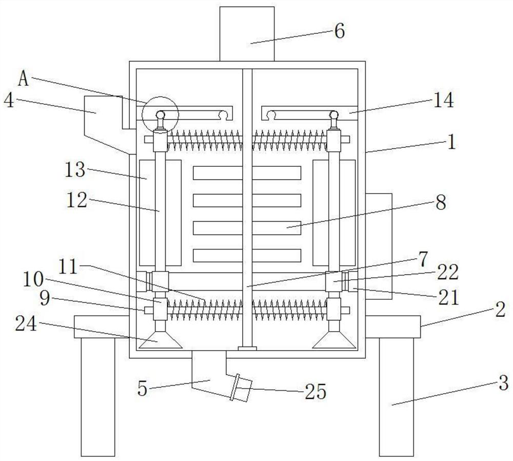
[0021] Please refer to the figure, in an embodiment of the present invention, a variable-diameter paint stirring and mixing device for construction includes a housing 1, a base 2, legs 3, a feed hopper 4, a discharge pipe 5, a motor 6 and a drive shaft 7 The base 2 is horizontally fixed on the bottom of the side wall of the housing 1, and the legs 3 are fixedly installed on the underside of the base 2 to support the housing 1; the top of the side wall of the housing 1 is connected with a feed hopper 4, Paint raw materials are loaded into the housing 1 from the feed hopper 4, and the bottom of the housing 1 is connected with a discharge pipe 5, and a valve 25 is installed on the discharge pipe 5, and the mixed paint is discharged from the discharge pipe 5. Tube 5 exits.

[0022] The motor 6 is coaxially fixed on the top of the housing 1, and the lower end of the output shaft of the motor 6 is coaxially fixedly connected with a vertical transmission shaft 7, and the lower end of...

Embodiment 2

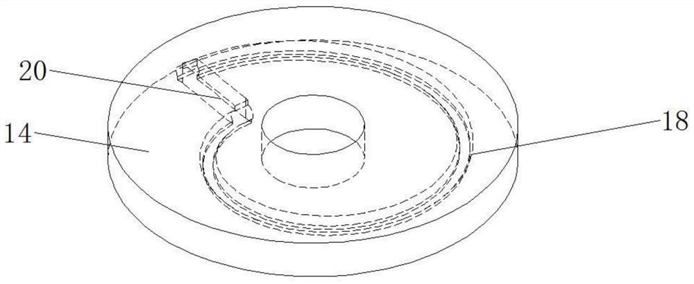
[0025] On the basis of Embodiment 1, a horizontal gear 22 is coaxially fixed on the outer side of the variable-diameter stirring shaft 12, and a lower guide plate 21 is fixedly installed on the inner wall of the housing 1 corresponding to the gear 22, and the inside of the lower guide plate 21 It is a hollow structure, and the shape of the inner wall corresponds to the vortex structure of the vortex chute 18. On the inner wall of the lower guide plate 21, a rack 23 meshing with the gear 22 is fixedly arranged. Rotate around the central axis during the movement of the shape structure to improve the stirring effect on the internal raw materials.

[0026]When in use, load the raw materials from the feed hopper 4 into the housing 1, start the motor 6, the motor 6 drives the transmission shaft 7 to rotate in the housing 1, and the main stirring blade 8 on the transmission shaft 7 stirs the raw materials inside Simultaneously, the transmission shaft 7 drives the support guide rod 9 ...


PUM


Abstract

The invention relates to the field of buildings, and particularly discloses a variable-diameter coating stirring and mixing device for buildings. The device comprises a shell, a base, support legs, afeed hopper, a discharge pipe, a motor and a transmission shaft, horizontal supporting guide rods are fixed to the upper end and the lower end of the transmission shaft correspondingly, a vertical sleeve is slidably mounted on each supporting guide rod, each supporting guide rod is sleeved with a horizontal supporting spring, a vertical variable-diameter stirring shaft is arranged in the two sleeves corresponding to each other up and down in a penetrating mode, and a plurality of auxiliary stirring blades are fixedly mounted on the variable-diameter stirring shaft. A circle of horizontal vortex-shaped sliding groove is formed in a guide supporting plate, and two ends of the vortex-shaped sliding groove communicate with each other through a communicating groove. Stirring is conducted through the variable-diameter stirring shaft capable of moving in the horizontal direction, in the process of moving around the transmission shaft, variable-diameter movement is conducted along the vortex-shaped sliding groove, the variable-diameter stirring shaft vertically moves in the radial direction, the stirring range is changed, and the coverage range of the variable-diameter stirring shaft is larger.

Description

technical field [0001] The invention relates to the field of construction, in particular to a stirring and mixing device for variable-diameter paint used in construction. Background technique [0002] The paint mixing device is a common device for mixing paints for architectural decoration. With the rapid development of society, there are more and more types of architectural paints. It is often necessary to mix different paints when decorating buildings, so people invented Paint mixing device. [0003] The paint mixing device is mainly used for paint mixing and toning. The existing structure of the paint mixing device has a complex structure and a single function. Generally, it only rotates in one direction in the paint mixing tank, resulting in uneven paint mixing, or making the mixing The color paste in the kettle is mixed with the white base paint in the kettle, and the color is uneven. Therefore, it is necessary to improve existing paint mixing devices. Contents of t...

Claims


Application Information

Patent Timeline
Patent Type & Authority Applications(China)
IPC IPC(8): B01F7/18B01F11/00
CPCB01F27/90B01F31/44B01F2101/30
Inventor 李士伟
Owner 李士伟
Features
  • Generate Ideas
  • Intellectual Property
  • Life Sciences
  • Materials
  • Tech Scout
  • Unparalleled Data Quality
  • Higher Quality Content
  • 60% Fewer Hallucinations
Learn More