

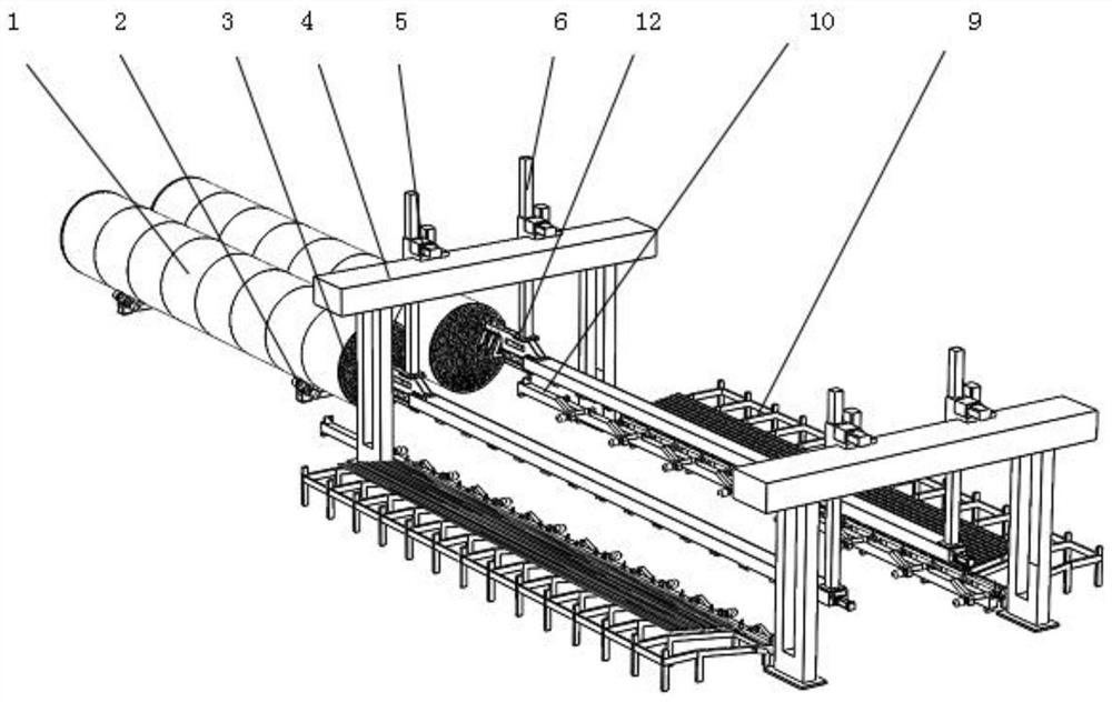
Automatic tube penetrating equipment for tube type heat exchangers
A tube-and-tube heat exchanger and automatic threading technology, which is applied in heat exchange equipment, metal processing equipment, feeding devices, etc., can solve the problems of high labor intensity, consumption, and large pipe resistance of operators, and save manufacturing costs , improve the efficiency of pipe threading, and realize the effect of automation
- Summary
- Abstract
- Description
- Claims
- Application Information
AI Technical Summary
Problems solved by technology
Method used
Image

Examples
Embodiment 1
[0048] Embodiment 1 (as Figure 3-5 shown)
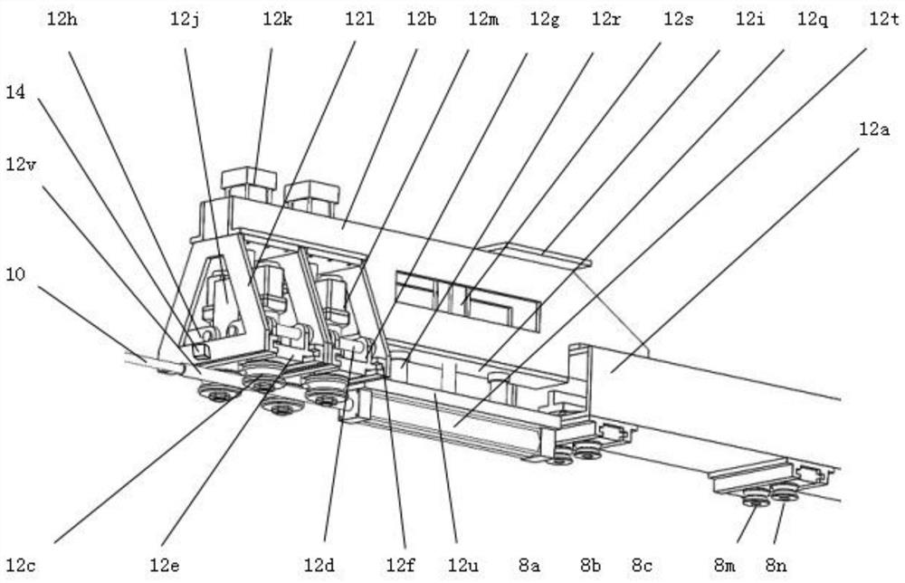
[0049] The pipe grasping and pipe threading driving device includes a first pipe grasping device 8 and a roller-driven pipe threading device 12. The roller-driven pipe threading device 12 includes a first beam 12a. The lower end of the first beam 12a is a steel plate plane, and both sides are reinforced plates. The middle is a hollow structure, and a first lifting column connecting plate 12i is respectively provided at the front and rear ends above the first beam 12a, and the lifting column 6 is connected with bolts thereto.
[0050] The front end of the first crossbeam 12a is equipped with a driving mechanism mounting frame 12b, and the lower end of the driving mechanism mounting frame 12b is provided with two arc-shaped driving wheel guide grooves 12f, and the middle of the two arc-shaped driving wheel guiding grooves 12f is symmetrically installed with an arc-shaped driving wheel guide. Slide block 12e, arc driving wheel guide s...
Embodiment 2
[0062] Embodiment 2 (as Figure 6-8 shown)
[0063] The pipe grasping and pipe threading drive device includes a second pipe grasping device 13 and a sprocket driven pipe threading device 7. The sprocket driven pipe threading device 7 includes a second beam 7a, the second beam 7a is welded by steel plate or section steel, and the second beam 7a is welded by steel plate or section steel. The lower end of the second beam 7a is a steel plate plane, both sides are reinforcing plates, and the middle is a hollow structure. A second lifting column connecting plate 7m is respectively provided at the front and rear ends of the second beam 7a, and the lifting column 6 is connected with bolts.
[0064] A linear guide rail mounting seat 7n is installed in the middle of the bottom of the second beam 7a, and a linear guide rail 7i and a linear guide rail slider 7j passing through the front and back are installed on the linear guide rail mounting seat 7n. An L-shaped push tube arm 7k is inst...
PUM
 Abstract
Description
Claims
Application Information