
Positioning device for assembling collecting pipe plug cap

A technology for positioning devices and headers, applied to cleaning methods and appliances, cleaning methods using gas flow, and dust removal, etc., can solve problems such as the single function of the cleaning mechanism, achieve dust-proof treatment, and increase the cleaning surface of the purge , The effect of rapid exhaust and heat dissipation

Pending Publication Date: 2021-01-26
合肥悦丰机械科技有限公司
View PDF0 Cites 0 Cited by
  • Summary
  • Abstract
  • Description
  • Claims
  • Application Information

AI Technical Summary

Problems solved by technology

[0004] The purpose of the present invention is to provide a positioning device for assembling a manifold plugging cap, so as to solve the problem that the existing positioning device for assembling a manifold plugging cap proposed in the above-mentioned background technology is inconvenient to collect scraps on the surface of the processing table during use. Auxiliary cleaning of parts, and the general cleaning mechanism has a single function, which makes it inconvenient to quickly collect and clean the device in an all-round way

Method used

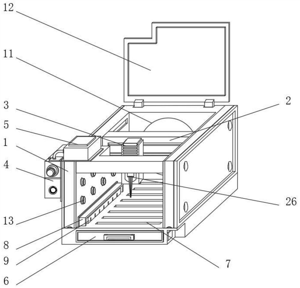
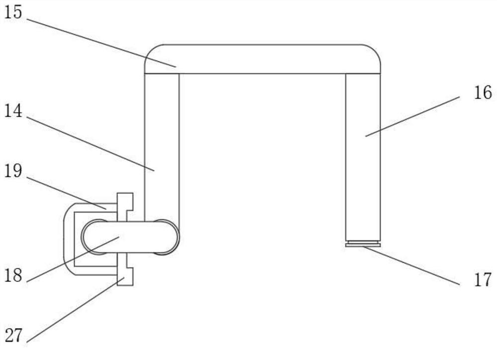
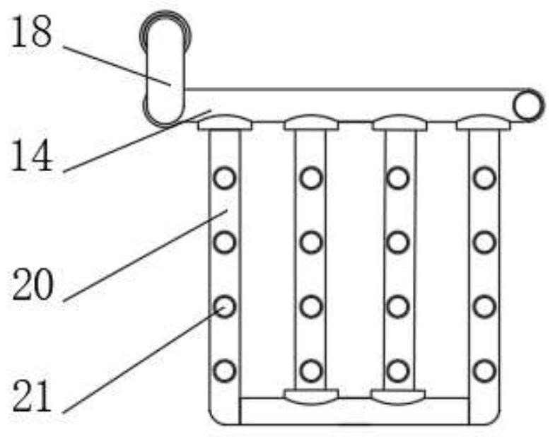

Image

  • Positioning device for assembling collecting pipe plug cap
  • Positioning device for assembling collecting pipe plug cap
  • Positioning device for assembling collecting pipe plug cap

Examples


Embodiment Construction

[0027] The following will clearly and completely describe the technical solutions in the embodiments of the present invention with reference to the accompanying drawings in the embodiments of the present invention. Obviously, the described embodiments are only some, not all, embodiments of the present invention.

[0028] In describing the present invention, it should be understood that the terms "upper", "lower", "front", "rear", "left", "right", "top", "bottom", "inner", " The orientation or positional relationship indicated by "outside", etc. is based on the orientation or positional relationship shown in the drawings, and is only for the convenience of describing the present invention and simplifying the description, rather than indicating or implying that the referred device or element must have a specific orientation, so as to Specific orientation configurations and operations, therefore, are not to be construed as limitations on the invention.

[0029] refer to Figure ...


PUM


Abstract

The invention discloses a positioning device for assembling a collecting pipe plug cap. The positioning device comprises an assembling and positioning device main body and a blowing device, wherein anassembling mechanism is fixedly mounted on the assembling and positioning device main body; the blowing device is fixedly mounted on the side wall of the assembling and positioning device main body;and the blowing device comprises a first blowing guide pipe and a second blowing guide pipe which are symmetrically mounted on the inner walls of the two sides of the assembling and positioning devicemain body. By designing the blowing device mounted on the assembling and positioning device main body, blowing treatment on crushed aggregates gathered on the assembling and positioning device main body is achieved; by means of the first blowing guide pipe and the second blowing guide pipe which are symmetrically distributed on the assembling and positioning device main body, all-directional cleaning on the position of an assembling table on the assembling and positioning device main body is achieved; And by designing a collecting mechanism mounted at the bottom of the inner side of the assembling and positioning device main body, centralized collection of the cleaned crushed aggregates is achieved, and treatment of the collected crushed aggregates is facilitated.

Description

technical field [0001] The invention belongs to the technical field of collecting pipe blocking cap processing, and in particular relates to a positioning device for assembling a collecting pipe blocking cap. Background technique [0002] The manifold is one of the important components in the pipeline system. The main function of the manifold is that the fluorine in the air conditioner is compressed by the compressor to produce a high-temperature and high-pressure liquefied gas, which is cooled and condensed by the condenser to become a low-temperature and high-pressure liquid. Into the header header flow. [0003] When the existing positioning device for assembly of the collecting pipe plug cap needs to be drilled and positioned, most of the clamping parts are manually adjusted for auxiliary clamping, which is extremely time-consuming and labor-intensive. When assembling accessories, a large amount of debris accumulates on the surface of the processing table, causing the c...

Claims


Application Information

Patent Timeline
Patent Type & Authority Applications(China)
IPC IPC(8): B23B41/00B23B39/14B23B47/00B23Q11/00B23Q11/08B08B5/02B08B13/00B08B15/04
CPCB23B41/00B23B47/00B23B39/14B23Q11/00B23Q11/08B23Q11/0042B23Q11/0032B23Q11/0067B08B5/02B08B13/00B08B15/04
Inventor 谷明良
Owner 合肥悦丰机械科技有限公司
Learn More