Supercharge Your Innovation With Domain-Expert AI Agents!

Optical fiber preform manufacturing apparatus and method for shrinkage and closing of deposited tube

A production device and production method technology, applied in optics, light guides, optical components, etc., can solve problems such as prolonged processing time, deformed geometric structure of deposition tubes, and decreased optical performance of finished optical fibers.

Inactive Publication Date: 2003-10-01
SAMSUNG ELECTRONICS CO LTD
View PDF0 Cites 0 Cited by
  • Summary
  • Abstract
  • Description
  • Claims
  • Application Information

AI Technical Summary

Problems solved by technology

For example, deformed geometry of the deposition tube, reduced optical performance of the finished fiber, and increased processing time

Method used


Image

  • Optical fiber preform manufacturing apparatus and method for shrinkage and closing of deposited tube
  • Optical fiber preform manufacturing apparatus and method for shrinkage and closing of deposited tube
  • Optical fiber preform manufacturing apparatus and method for shrinkage and closing of deposited tube

Examples


Embodiment Construction

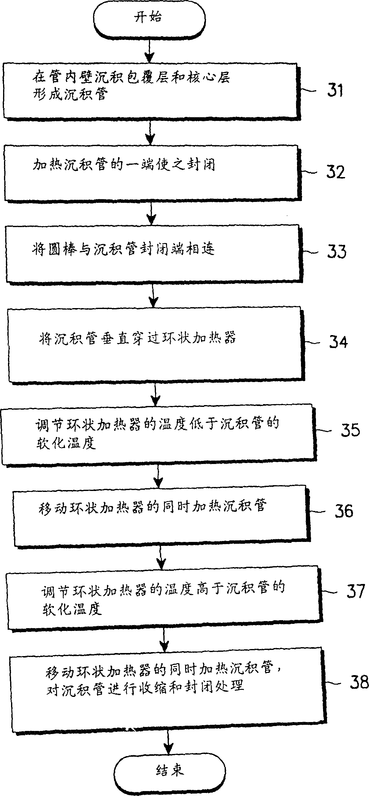
[0015] The invention discloses an optical fiber preforming production device and method, which comprises using the reaction product of raw material gas to deposit on the inner wall of a preforming tube to generate a deposition tube, and shrink and seal the deposition tube to obtain a preformed optical fiber . The deposition process is performed by an ordinary method such as the MCVD method. The shrinking and sealing process can be carried out simply and quickly by adopting the technology of the present invention.

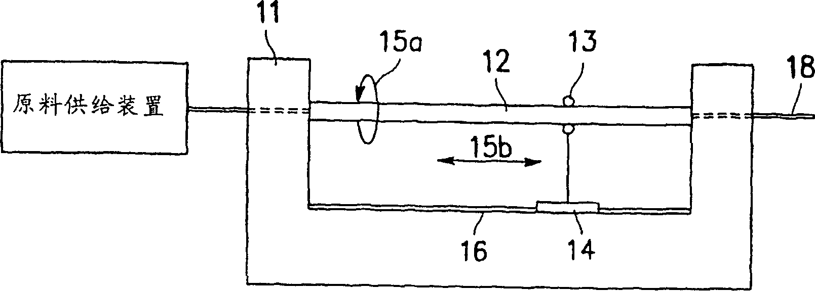
[0016] figure 1 is a general diagram of a deposition apparatus suitable for the MCVD method. The device is used to deposit the reaction product of the raw material gas on the inner wall of the preformed tube. see figure 1 , the lathe 11 is used to support the preformed tube 12 . Viewed in the longitudinal and radial directions, the heating device 14 locally heats the preformed tube 12 . exist figure 1 In , the area where the preformed tube is heated is indica...


PUM


Abstract

Apparatus and method for producing optical fiber preforms with means for shrinking and closing deposition tubes suitable for respective processes, which can shorten processing time and at the same time reduce the amount of OH that penetrates from the preform tube into the glass component of the deposition tube , thereby reducing light loss. In the optical fiber preforming production device and method, the following operations are included: setting the temperature of the annular heater to be lower than the softening temperature of the deposition tube, while maintaining a certain temperature to move the annular heater, consuming the internal heat of the deposition tube Pollutants, set the temperature of the annular heater not lower than the softening temperature of the deposition tube, shrink and seal the deposition tube while maintaining a certain temperature.

Description

technical field [0001] The invention introduces a production device and method for preformed optical fiber, and elaborates in detail a production device for preformed optical fiber and a method for shrinking and sealing a deposition tube with higher efficiency. Background technique [0002] The production of optical fibers by the modified chemical vapor deposition (MCVD) method is well known. In the deposition process corresponding to the MCVD method, a deposition layer is deposited in the form of a tube on the inner wall of the preformed tube, and as the thickness of the deposition layer increases, the deposition tube itself shrinks. For this reason, furnaces with low flame pressure and large heating area are mostly used in the deposition process. The large heating area of ​​the furnace makes it easier to transmit heat to the inner wall of the preformed tube, thereby improving the deposition efficiency. On the other hand, low flame pressure reduces unnecessary shrinkage o...

Claims


Application Information

Patent Timeline
Patent Type & Authority Patents(China)
IPC IPC(8): C03B37/027C03B37/012C03B37/018G02B6/00
CPCC03B37/01248C03B37/01257C03B37/01853C03B37/01869G02B6/00
Inventor 吴成国徐晚硕扬镇成都文显
Owner SAMSUNG ELECTRONICS CO LTD
Features
  • R&D
  • Intellectual Property
  • Life Sciences
  • Materials
  • Tech Scout
  • Unparalleled Data Quality
  • Higher Quality Content
  • 60% Fewer Hallucinations
Learn More