Surface marking device for machining mechanical parts

A technology of mechanical parts and placement table, applied in the field of parts processing, can solve the problems of single structure, prone to dislocation, jitter, unclear marking, etc., and achieve the effect of ensuring stability and avoiding dislocation

Inactive Publication Date: 2021-01-26
邱海姑
View PDF1 Cites 1 Cited by
  • Summary
  • Abstract
  • Description
  • Claims
  • Application Information

AI Technical Summary

Problems solved by technology

[0003] After retrieval, China Patent Network discloses a surface marking device for mechanical parts processing (public announcement number CN107262554A), in which a fixed table is fixedly connected to the top of the bottom plate, and a motor is fixedly connected to the top of the fixed table, and the output shaft of the motor The surface is covered with a first pulley, the surface of the first rotating rod close to the motor is covered with a second pulley, the surface of the second pulley is connected to the first pulley through a belt, and the surface of the first rotating rod far away from the motor is covered with a Turntable, this type of device ensures the marking depth of the marking plate on the mechanical parts, avoids the unqualified products caused by the insufficient depth of the standard, and reduces the processing cycle of the mechanical parts, but the structure of this type of device is relatively Single, misalignment and vibration are very easy to occur during the marking process, and during the marking process, the marking stability of mechanical parts is insufficient, and the marking is easy to appear unclear

Method used


Image

  • Surface marking device for machining mechanical parts
  • Surface marking device for machining mechanical parts
  • Surface marking device for machining mechanical parts

Examples


Embodiment Construction

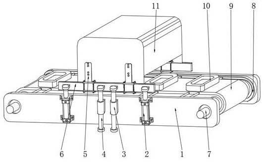
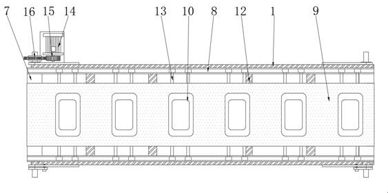
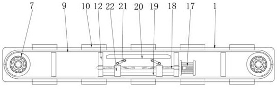
[0022] see Figure 1~5 , in an embodiment of the present invention, a surface marking device for processing mechanical parts includes a transport frame 1, hydraulic push rods 2 are symmetrically fixed on the front and rear sides of the transport frame 1, and the front and rear sides of the transport frame 1 are located at The middle position is symmetrically fixed with a positioning sliding sleeve 3, the inner side of the positioning sliding sleeve 3 penetrates and engages the limit sliding rod 4, the inner diameter of the positioning sliding sleeve 3 matches the outer diameter of the limiting sliding rod 4, and the limiting sliding rod 4 The length of the hydraulic push rod 2 is the same as the telescopic length of the hydraulic push rod 2. When marking the mechanical parts, the telescopic end of the hydraulic push rod 2 lifts up and down. The support plate 6 moves up and down smoothly to adjust the printing height and position of the printing needle 26 .

[0023] The telesc...


PUM


Abstract

The invention relates to the technical field of part machining, and discloses a surface marking device for machining mechanical parts. A marking mechanism is fixed to the telescopic end of a hydraulicpush rod, supporting plates are symmetrically fixed to the inner side of a conveying frame, printing supporting mechanisms are arranged on the inner sides of the supporting plates, transmission mainshafts are symmetrically connected to the positions, located at the two ends, of the inner side of a conveying frame, the outer sides of the transmission main shafts are connected with a conveying belt, and placing tables are fixed to the upper portion of the conveying belt. According to the surface marking device for mechanical part machining, supporting guide rods are subjected to double sleeving positioning through clamping rollers and pushing sliding sleeves in the marking mechanism, under transmission conveying of transmission toothed belts, printing needle heads can be driven to stably and accurately slide, the situations of dislocation and shaking in the marking process are avoided, the placing tables are mechanically conveyed through the conveying belt in the marking process, and under the supporting and lifting of the printing supporting mechanisms, the mechanical parts can be in a stable marking environment.

Description

technical field [0001] The invention relates to the technical field of parts processing, in particular to a surface marking device for processing mechanical parts. Background technique [0002] Date code marking is when the computer controls the printing needle to move according to a certain trajectory in the X, Y two-dimensional plane, while the printing needle performs high-frequency impact movement under the action of compressed air, so as to print a mark with a certain depth on the workpiece. Widely used in marking and marking of various molding machinery parts. [0003] After retrieval, China Patent Network discloses a surface marking device for mechanical parts processing (public announcement number CN107262554A), in which a fixed table is fixedly connected to the top of the bottom plate, and a motor is fixedly connected to the top of the fixed table, and the output shaft of the motor The surface is covered with a first pulley, the surface of the first rotating rod cl...

Claims


Application Information

Patent Timeline
Patent Type & Authority Applications(China)
IPC IPC(8): B44B5/00B44B5/02
CPCB44B5/0052B44B5/022
Inventor 邱海姑
Owner 邱海姑
Why Eureka
Try Eureka