Molten aluminum slag removing device in aluminum alloy machining and using method thereof

A technology of aluminum alloy and aluminum liquid, which is applied in the field of aluminum alloy processing equipment, can solve the problems of inability to realize high-efficiency slag removal of aluminum liquid, inability to evenly sprinkle and separate slag-forming agents, etc., to facilitate collection and centralized cleaning, and realize left-right adjustment , to achieve the effect of fixing and dismantling

Inactive Publication Date: 2021-01-26
HENAN VOCATIONAL COLLEGE OF WATER CONSERVANCY ANDENVIRONMENT
View PDF7 Cites 4 Cited by
  • Summary
  • Abstract
  • Description
  • Claims
  • Application Information

AI Technical Summary

Problems solved by technology

[0002] Aluminum is a silver-white light metal, which is the most abundant metal element in the earth’s crust. Aluminum is an essential metal for aluminum alloy casting. In the process of aluminum casting, in order to reduce impurities in aluminum liquid and improve the quality of aluminum, by using The slagging agent effectively separates the aluminum metal from the impurities, and makes the impurities form scum, and then salvages the scum. In the prior art, the patent disclosure of the authorized publication number CN 111174580 A relates to an aluminum alloy used for casting production. The liquid slag removal device includes a support column, and a guide rail is fixedly connected to the left end surface of the support column. slag, the lower side of the guide rail is provided with a transmission device located on the right side of the slag removal device, and the left end surface of the support column is provided with a vibration slag removal device located at the lower side of the transmission device, the vibration slag removal device It is used to remove the scum fished out by the slag removal device. The left side of the support column is provided with a scum storage device located on the lower side of the vibrating slag removal device. The traditional aluminum liquid cleaning device cannot evenly distribute the slag forming agent. Sprinkled into the aluminum liquid, the waste in the aluminum liquid cannot be separated from the aluminum liquid quickly, and the efficient slag removal of the aluminum liquid cannot be realized. Therefore, in order to solve the above problems, we have designed a device for removing slag from the aluminum liquid in aluminum alloy processing.

Method used


Image

  • Molten aluminum slag removing device in aluminum alloy machining and using method thereof
  • Molten aluminum slag removing device in aluminum alloy machining and using method thereof
  • Molten aluminum slag removing device in aluminum alloy machining and using method thereof

Examples


Embodiment 1

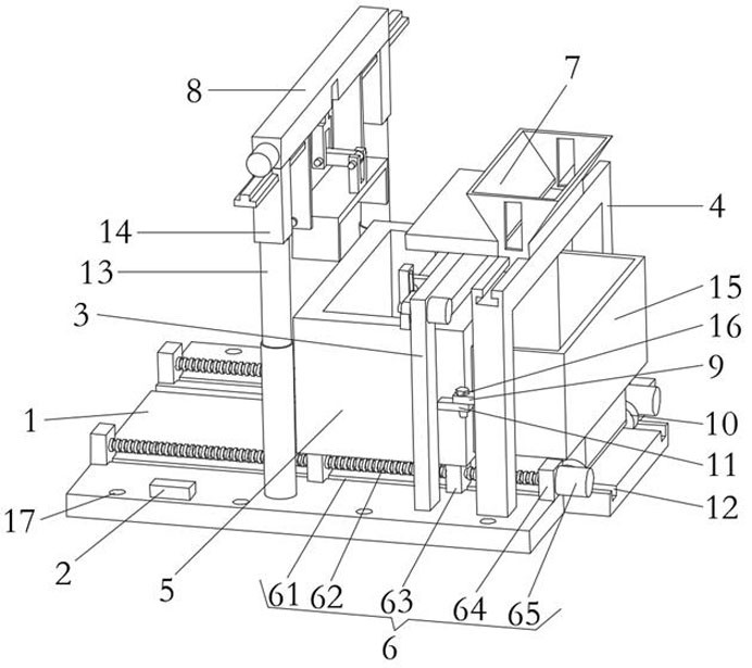
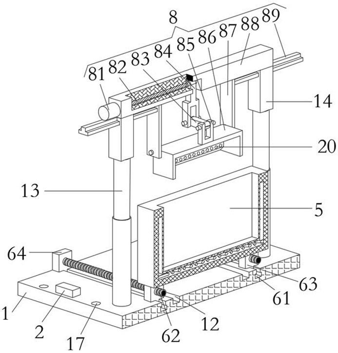
[0027] A liquid aluminum slag removal device in aluminum alloy processing, comprising a base plate 1, an adjustment structure 6, a blanking structure 7 and a slag removal structure 8, the upper surface of the base plate 1 is symmetrically provided with uniformly distributed installation holes 17 at the front and rear ends, and the base plate 1 The first U-shaped frame 3 and the second U-shaped frame 4 are respectively arranged on the left side of the upper surface, the first U-shaped frame 3 is located on the left side of the second U-shaped frame 4, and the middle part of the upper surface of the bottom plate 1 is symmetrically provided with electric push rods 13. The upper end of the telescopic end of the electric push rod 13 is equipped with a vertical plate 14, which is connected to the installation part through the installation hole 17 by bolts, so as to realize the installation and fixation of the bottom plate 1 and the structure above it. The first U-shaped frame 3 and th...

Embodiment 2

[0030] The difference between this embodiment and Embodiment 1 is:

[0031] In this embodiment, the adjustment structure 6 includes a first chute 61, a screw rod 62, a slider 63, a square plate 64, and a first motor 65. The square plate 64 is symmetrically arranged on the left and right sides of the upper surface of the bottom plate 1, and the right side The right sides of the square plates 64 are all provided with a first motor 65, and the horizontally corresponding square plates 64 are connected with a screw mandrel 62 through bearing rotation, and the right ends of the screw mandrels 62 are respectively output by the corresponding first motor 65 through a coupling. The left end of the shaft is fixedly connected, and the upper surface of the bottom plate 1 is symmetrically provided with a first chute 61, and the inside of the first chute 61 is slidably connected with a slider 63, and the threaded holes at the upper end of the slider 63 are respectively threaded with the corre...

Embodiment 3

[0034] The difference between this embodiment and Embodiment 1 is:

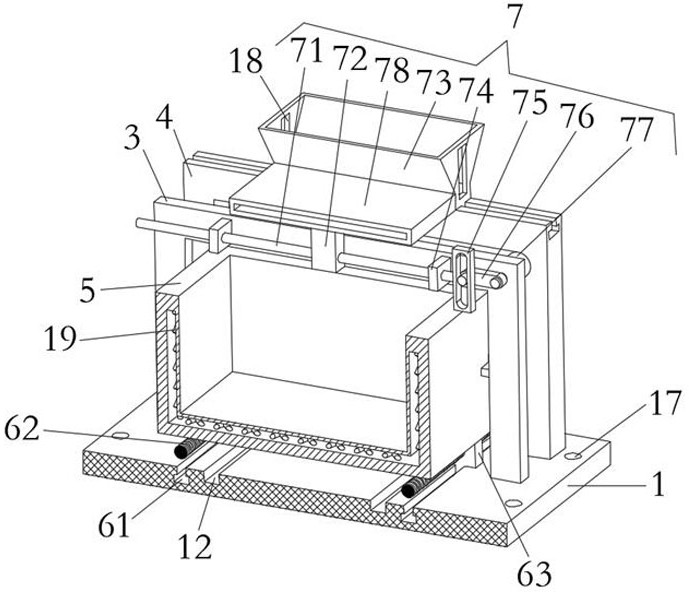
[0035] In this embodiment, the blanking structure 7 includes a round rod 71, a fixed block 72, a funnel 73, a support block 74, a square frame 75, a swing rod 76, a second motor 77 and a diversion groove 78, and the second motor 77 is arranged on the second motor 77. The front end of the horizontal plate body right side of a U-shaped frame 3, the output shaft of the second motor 77 is connected with the plate body through hole of the first U-shaped frame 3 through the bearing and extends to the left side of the first U-shaped frame 3, The end of the output shaft of the second motor 77 is provided with a swing lever 76, and the slider at the lower end of the funnel 73 is slidably connected with the chute on the upper surface of the second U-shaped frame 4, and the opening at the lower end of the left side of the funnel 73 is provided with a diversion groove 78 , the lower end of the left side bottom surface of...


PUM


Abstract

The invention discloses a molten aluminum slag removing device in aluminum alloy machining and a using method thereof. The molten aluminum slag removing device in aluminum alloy machining comprises abottom plate, an adjusting structure, a discharging structure and a slag removing structure, evenly-distributed mounting holes are symmetrically formed in the front end and the rear end of the upper surface of the bottom plate, a first U-shaped frame and a second U-shaped frame are arranged on the left side of the upper surface of the bottom plate, the first U-shaped frame is located on the left side of the second U-shaped frame, electric push rods are symmetrically arranged in the middle of the upper surface of the bottom plate, and vertical plates are arranged at the upper ends of the extendable ends of the electric push rods; the adjusting structure is arranged on the upper surface of the bottom plate, a molten aluminum groove is formed in the upper end of the adjusting structure, and evenly-distributed electric heating wires are arranged in a cavity of the molten aluminum groove; and the discharging structure is arranged on a frame body of the first U-shaped frame, and the slag removing structure is arranged at the upper ends of the vertical plates. According to the molten aluminum slag removing device in aluminum alloy machining, waste in molten aluminum can be rapidly separated from the molten aluminum and floats to the surface of the molten aluminum, and efficient slag removing of the molten aluminum is achieved.

Description

technical field [0001] The invention relates to the technical field of aluminum alloy processing equipment, in particular to a liquid aluminum slag removal device in aluminum alloy processing and a use method thereof. Background technique [0002] Aluminum is a silver-white light metal, which is the most abundant metal element in the earth's crust. Aluminum is an essential metal for aluminum alloy casting. In the process of aluminum casting, in order to reduce impurities in aluminum liquid and improve the quality of aluminum, by using The slagging agent effectively separates the aluminum metal from the impurities, and makes the impurities form scum, and then salvages the scum. In the prior art, the patent disclosure of the authorized publication number CN 111174580 A relates to an aluminum alloy for casting production. The liquid slag removal device includes a support column, and a guide rail is fixedly connected to the left end surface of the support column. slag, the lowe...

Claims


Application Information

Patent Timeline
Patent Type & Authority Applications(China)
IPC IPC(8): C22C1/06C22C21/00C22B21/06C22B9/10F27D3/15F27D19/00
CPCC22B9/103C22B21/06C22C1/06C22C21/00F27D3/1554F27D19/00Y02P10/20
Inventor 赵驭阳
Owner HENAN VOCATIONAL COLLEGE OF WATER CONSERVANCY ANDENVIRONMENT
Why Eureka
Try Eureka