Intelligent false support rod device for high-speed wind tunnel

A high-speed wind tunnel and rod device technology, which is applied in the direction of measuring devices, machine/structural component testing, instruments, etc., can solve the problem of collision between the model and the fake tail rod, and the relative position relationship between the model and the tail rod cannot be completely consistent, etc. problem, to achieve the effect of collision avoidance

Inactive Publication Date: 2021-01-26
INST OF HIGH SPEED AERODYNAMICS OF CHINA AERODYNAMICS RES & DEV CENT
View PDF6 Cites 6 Cited by
  • Summary
  • Abstract
  • Description
  • Claims
  • Application Information

AI Technical Summary

Problems solved by technology

However, under the existing test technology conditions, the relative positional relationship between the model and the tail strut cannot be completely consistent. The reason is that the tail strut It will produce large elastic deformation; while the support interference test of the tail support, the aerodynamic load on the model can only cause large elastic deformation of the balance and auxiliary support system, and the aerodynamic load on the dummy tail support is smaller than that of the model Therefore, the elastic deformation of the false tail strut is also small, so the positional relationship of the fake tail strut relative to the model is different from that of the real tail strut relative to the model in the conventional wind tunnel test, and the false tail strut has not been accurately simulated. The interference of the real tail strut on the model, when the angle of attack of the model gradually increases, the aerodynamic load also gradually increases, eventually causing the model to collide with the fake tail strut. Therefore, the existing support interference test of the tail strut can only within the angle of attack range

Method used


Image

  • Intelligent false support rod device for high-speed wind tunnel
  • Intelligent false support rod device for high-speed wind tunnel

Examples


Embodiment 1

[0028] The implementation process of this embodiment is as follows:

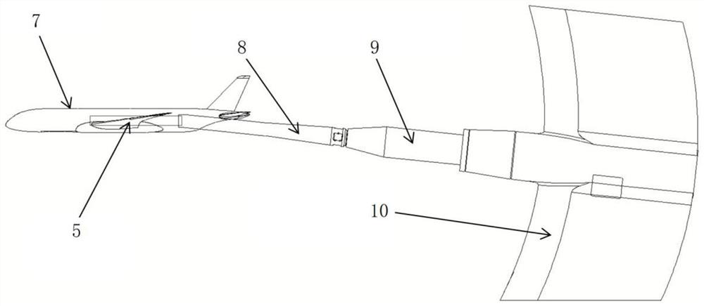
[0029] 1. In the conventional tail brace dynamometer wind tunnel test, if figure 2 As shown, the model 7 is connected to the real tail strut 8 through the balance 5, the real tail strut 8 is connected to the direct head 9, and the direct head 9 is connected to the wind tunnel scimitar mechanism 10; The relative position of data, model 7 and true tail strut 8.

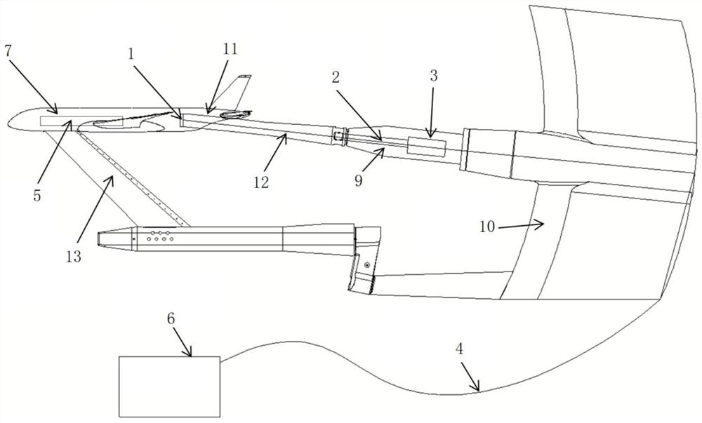
[0030] 2. In the support interference test of the tail support, such as figure 1 As shown, the false tail strut 12 of the present invention is used to replace the original real tail strut 8, the model 7 is connected to the blade support 13 through the balance 5, the blade support 13 is connected to the wind tunnel machete mechanism 10, and the false tail strut 12 It is connected with the direct head 9, and the direct head 9 is connected with the scimitar mechanism 10 of the wind tunnel.

[0031] 3. Utilize the transmission mechanism 2 and driver 3...


PUM


Abstract

The invention discloses an intelligent false support rod device for a high-speed wind tunnel. The device comprises a displacement sensor, a transmission mechanism, a driver, a measurement and controlcable for connecting the displacement sensor, the transmission mechanism and the driver, and a subsystem for controlling the displacement sensor, the transmission mechanism and the driver, the displacement sensor is mounted at the head of the false tail support rod to monitor a gap between the false tail support rod and the model; and the transmission mechanism and the driver are installed in an inner cavity of the straight joint, and the driver drives the transmission mechanism to drive the false tail supporting rod to move relative to the model. The subsystem is connected with a measurementand control system of the high-speed wind tunnel and shares one computer with the measurement and control system of the high-speed wind tunnel. The device can realize following motion of the false tail support rod relative to the model, avoids collision between the model and the false tail support rod, and obtains more accurate tail support interference quantity under a larger attack angle; and the false tail support rod can be controlled to move according to an instruction, a gap between the false tail support rod and the model is changed, and the influence of the gap on support interferenceis studied.

Description

technical field [0001] The invention belongs to the technical field of high-speed wind tunnel tests, and in particular relates to an intelligent false support rod device used in high-speed wind tunnels. Background technique [0002] In high-speed wind tunnel tests, support interference has been a long-standing problem. In order to obtain accurate and reliable support interference data through experimental means, a special support interference wind tunnel test is required. The support interference wind tunnel test needs to design a set of auxiliary support devices and a set of dummy struts. [0003] Usually, the support interference of the tail support in the high-speed wind tunnel is the least, so the main support form in the high-speed wind tunnel is generally the tail support. The support interference test device of tail support uses auxiliary supports such as abdominal blade support, strip support, wingtip double support, vertical tail support, etc. The secondary interfe...

Claims


Application Information

Patent Timeline
Patent Type & Authority Applications(China)
IPC IPC(8): G01M9/04G01M9/06
CPCG01M9/04G01M9/062
Inventor 苏继川李永红黄勇彭鑫李乾刘光远
Owner INST OF HIGH SPEED AERODYNAMICS OF CHINA AERODYNAMICS RES & DEV CENT
Why Eureka
Try Eureka