[0047]Example one
[0048]In some alternative embodiments, seefigure 1 ,figure 1 It is a schematic flowchart of a symmetric environment relocation method according to an embodiment of the present application.
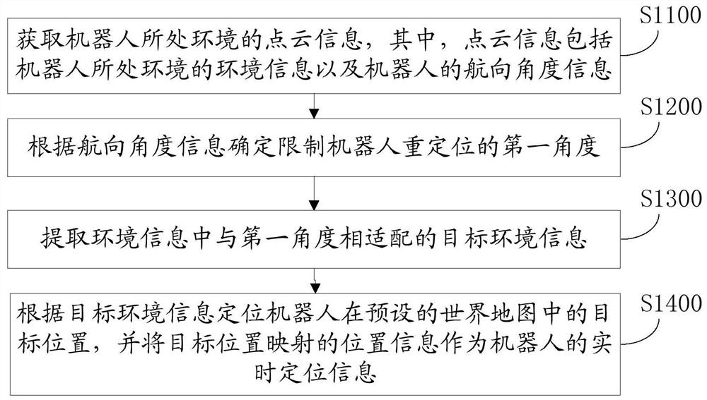
[0049]Such asfigure 1 As shown, this application provides a symmetric environment relocation method, including:
[0050]S1100. Acquire point cloud information of the environment where the robot is located, where the point cloud information includes environmental information of the environment where the robot is located and heading angle information of the robot;
[0051]Point cloud information can be environmental information collected by lidar. Lidar is a measurement equipment that integrates laser scanning and positioning and attitude determination systems. The lidar system includes a laser and a receiving system. The working principle is that the laser generates and transmits A beam of light pulse hits the object and is reflected back, and is finally received by the receiver. The receiver accurately measures the propagation time of the light pulse from emission to reflection. Since the speed of light is known, the propagation time can be converted into a measurement of the distance. Combining the height of the laser and the scanning angle of the laser, the three-dimensional coordinates X, Y, Z of each ground spot can be accurately calculated. Point cloud data refers to a set of vectors in a three-dimensional coordinate system. These vectors are usually expressed in the form of X, Y, and Z three-dimensional coordinates, and are generally mainly used to represent the outer surface shape of an object. Point cloud data is also It can represent the RGB color, gray value, depth, and segmentation result of a point.
[0052]The point cloud information includes the environment information of the robot's environment and the robot's heading angle information. During implementation, the environment contour information collected by the lidar point cloud can be used as the environment information of the robot's environment, and the robot's heading angle information is sweeping. The robot’s custom orientation angle can be measured by the IMU on the map. The orientation of the robot when it is turned on determines the zero point of the IMU’s heading angle. After the map is created, the IMU’s heading angle is consistent with the world map. The included angles of the world axis (such as X, Y, Z axis) are fixed. IMU (Inertial Measurement Unit) is a device for measuring the three-axis attitude angle and acceleration of an object. Generally, IMU includes a three-axis gyroscope and a three-axis accelerometer. That is, when the machine starts up, the heading angle of the robot is calculated by the IMU algorithm, and the sweeping robot scans the environment information of the robot's environment through the lidar during the work process, and combines the environment information and heading angle information into point cloud information.
[0053]S1200: Determine the first angle that limits the robot's relocation according to the heading angle information;
[0054]S1300. Extract target environment information that is adapted to the first angle from the environment information;
[0055]The first angle of robot relocation is determined by the heading angle. During implementation, the sweeping robot collects environmental contours through the lidar point cloud by scanning the surrounding environment in all directions. By limiting the first angle of robot relocation, the robot can be restricted to The collection angle of environmental information or the use of restricted environmental information to determine the location of the robot.
[0056]S1400: Locate the target position of the robot on the preset world map according to the target environment information, and use the position information mapped to the target position as real-time positioning information of the robot.
[0057]The system limits the target environment information in the collected environment information according to the heading angle, and compares and matches the target environment information in the world map to locate the target position of the robot on the world map. The target position is the real-time positioning of the robot Position. In a symmetrical environment, the lidar point cloud scans the surrounding environment in all directions, which is prone to positioning errors. For example, in a rectangular room, the sweeping robot is located at any one of the four corners of the rectangle, and the robot and the corner When moving the robot to other corners, if the distance between the robot and the walls on both sides meets the positioning conditions, multiple overlapping positions will be generated. It is considered that the positions of the four corners are all before being moved. Position the position, but only one of the four corners is correct, and the remaining positions are wrong, making the robot incorrectly positioned to a symmetrical position.
[0058]The heading angle information is used to limit the first angle of the robot's relocation, so that the robot only uses the environmental information within the limited angle range. Please refer to 2.figure 2 It is a schematic diagram of the position of the robot in the rectangular environment of the symmetric environment relocation method of this application, such asfigure 2 As shown, the rectangular environment includes position A, position B, and position C, where position A is located at the lower left corner of the rectangular environment, position B is located at the lower right corner of the rectangular environment, position C is located in the middle of the rectangular environment, and the initial position of the robot is located at position A , When the robot is moved to position C, due to the characteristics of the lidar point cloud, the robot is determined to move to position C, and the cleaning trajectory is re-planned to complete the cleaning task; and when the robot is moved from position A At position B, for example, at position A, the distance between the robot and the walls on both sides is 2 cm. At position B, the distance between the robot and the walls on both sides is also 2 cm. At this time, the robot does not perform partial relocation and cannot complete the current cleaning. Task, resulting in an error in mapping. This application restricts the first angle of relocation of the robot. For example, the robot only scans the environmental information in the 90° angle range between the left and the lower side. When the robot is transported from position A to position B, the distance to the left wall of the robot changes At this time, the robot performs partial repositioning to filter out the only correct position.
[0059]In some embodiments, seeimage 3 ,image 3 It is a schematic diagram of the heading and position of the robot in the symmetric environment relocation method of this application, such asimage 3 As shown, the robot is in position 1 before being moved. Taking the IMU heading of the robot at position 1 as an example, the position of the sweeping robot on the world map is (X1, Y1, 45°); after the sweeping robot is being moved Placed in position 2, position 2 does not change the orientation of the robot. At this time, the heading of the IMU has not changed. The pose of the robot on the map is (X2, Y2, phi2). According to the corresponding relationship between the IMU and the pose angle, the current The pose angle of the robot phi2=45°; and according to the environmental information observed by the radar point cloud,figure 2 The position 3 in is also consistent with the result of point cloud matching, and the pose of the machine in the map is (X3, Y3, phi3). At this time, the angle calculated by the IMU algorithm is phi3=-170°, which is not the same as the heading angle of the IMU. Matches to eliminate position 3, which can effectively eliminate misaligned positions.
[0060]In this application, the point cloud information includes the environment information of the robot's environment and the heading angle information of the robot. The environment information is the environmental contour of the robot's environment obtained through the environment collection of the lidar point cloud, and the heading angle information is limited The first angle of the robot relocation, and then extract the target environment information corresponding to the first angle in the environment information, thereby limiting the environment contour of the robot relocation, so the target position of the robot on the world map can be located according to the target environment information, The target position is the real-time positioning position of the robot, which is screened out as a correct position by the angle of the heading angle and the pose of the robot, and the wrong symmetrical position is eliminated to realize the local repositioning of the sweeping robot in a symmetrical environment.