Charging docking mechanism

A docking mechanism and articulation technology, applied in the field of robotics, can solve problems such as difficulty in determining the order, difficulty in ensuring accurate position of the end, inconvenient height adjustment, etc., to achieve the effect of increasing the scope of application, facilitating docking, and improving the probability of successful docking

Pending Publication Date: 2021-01-26
STANDARD ROBOTS CO LTD
View PDF0 Cites 2 Cited by
  • Summary
  • Abstract
  • Description
  • Claims
  • Application Information

AI Technical Summary

Problems solved by technology

[0002] With the development of society and the advancement of science and technology, robots have been more and more widely used in current production and life. A robot is an intelligent device that independently controls movement and performs work automatically. It can accept commands from users and operate Pre-programmed programs can also act according to the principles and guidelines formulated by artificial intelligence technology; robots are generally driven by electricity and need to be charged, and automatic charging equipment for robots generally use fixed charging piles, and the docking structure is in the form of plugs. First, the female head is on the robot, and then the robot actively docks with the charging pile, and charging starts after the male and female heads are docked; due to errors in the positioning and control of the robot, the male and female heads are not in an ideal alignment state when they are docked, often There is a large angle and distance deviation
[0003] The existing solution is to enable the male head on the charging pile to float and self-adaptively correct the deviation between the male and female heads. The design of the floating mechanism is very critical. Whether the deviation can be successfully corrected directly determines whether the docking process is smooth and the docking is successful. Probability; the existing floating mechanism is a multi-degree-of-freedom mechanism composed of multiple linear guide rails, linear bearings and guide rods. This type of scheme is composed of linear motions in various directions to piece together the required degrees of freedom. Each degree of freedom is composed of Multiple springs return, the main disadvantages: (1) The structure is very complex, with multiple degrees of freedom stacked together, it is difficult to determine the sequence of each degree of freedom, so it is difficult to control the movement form of the end; (2) It is inconvenient to adjust the height in the up and down direction , it is difficult to adapt to the docking requirements of different heights; (3) There are too many levels of each degree of freedom, and the amount of shaking that is superimposed on the end of the gap is large, and it is difficult to ensure an accurate position at the end

Method used


Image

  • Charging docking mechanism
  • Charging docking mechanism
  • Charging docking mechanism

Examples


Embodiment 1

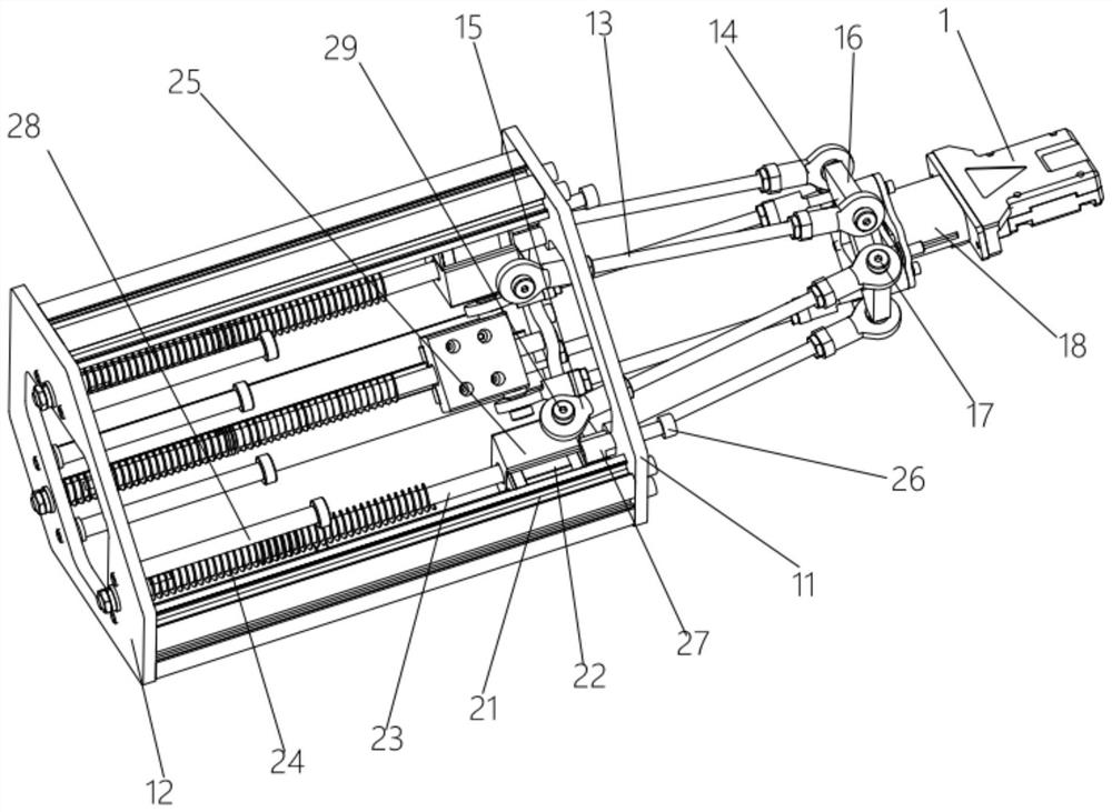
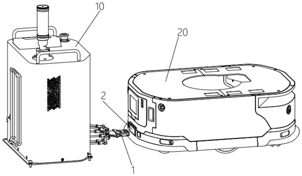
[0026] Such as Figure 1-2 As shown, the charging docking mechanism shown in this embodiment includes a base assembly, a male head 1 arranged in front of the base assembly, and a connecting rod assembly for connecting the base assembly and the male head 1. The base assembly includes front and rear parallel The front base plate 11 and the rear base plate 12 that are set are provided with three slides vertically arranged with the front base plate 11 and the rear base plate 12 at equidistant intervals between the front base plate 11 and the rear base plate 12. Rails 21, each slide rail 21 is provided with a slide block 22 matched with it, the slide block 22 can slide back and forth on the slide rail 21, and the connecting rod assembly includes three connecting rods with one end hinged on the slide block 22 The other end of the connecting rod group is hinged on the male head 1; in the above structure, the base assembly is installed on the charging pile 10, and the charging port 2 ...

Embodiment 2

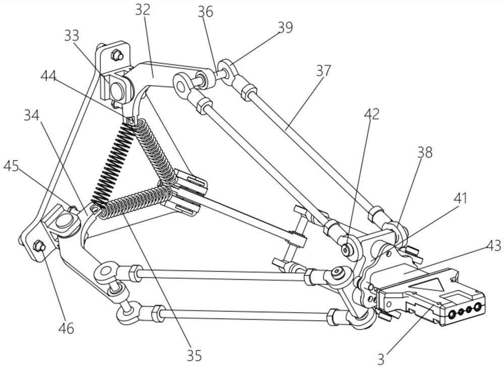
[0034] Such as Figure 3-4 As shown, the charging docking mechanism shown in this embodiment includes a base assembly, a male head 3 arranged in front of the base assembly, and a link assembly for connecting the base assembly and the male head 3. The base assembly includes a base The plate 31 is provided with three rotating arms 32 rotating on the base plate 31, and the connecting rod assembly includes three connecting rod groups, one end of which is hinged to the rotating arm 32, and the other end of the connecting rod group is hinged on the male head 3; In the above structure, the base plate 31 is installed on the charging pile 30, and the charging port 4 is provided on the robot 40. When the robot 40 needs to be charged, the robot 40 approaches the charging pile 30, and drives the charging port 4 to the male head 3. When the charging port 4 is aligned with the male head 3, the charging port 4 can be directly combined with the male head 3 to charge the robot 40. If the charg...


PUM


Abstract

The invention discloses a charging docking mechanism which comprises a base assembly, a male head arranged in front of the base assembly and a connecting rod assembly used for connecting the base assembly and the male head, at least three sliding blocks are arranged in the base assembly in a sliding mode, and the connecting rod assembly comprises a connecting rod set with one end hinged to the sliding blocks. The other end of the connecting rod group is hinged to the male head. According to the invention, the connecting rod assembly is utilized to provide degrees of freedom for the male jointto move in the front-back direction, the left-right direction and the up-down direction, so that the male head can be conveniently butted with the female head in the butting process.

Description

technical field [0001] The invention belongs to the technical field of robots, and in particular relates to a charging docking mechanism. Background technique [0002] With the development of society and the advancement of science and technology, robots have been more and more widely used in current production and life. A robot is an intelligent device that independently controls movement and performs work automatically. It can accept commands from users and operate Pre-programmed programs can also act according to the principles and guidelines formulated by artificial intelligence technology; robots are generally driven by electricity and need to be charged, and automatic charging equipment for robots generally use fixed charging piles, and the docking structure is in the form of plugs. First, the female head is on the robot, and then the robot actively docks with the charging pile, and charging starts after the male and female heads are docked; due to errors in the positio...

Claims


Application Information

Patent Timeline
Patent Type & Authority Applications(China)
IPC IPC(8): H01R13/631H02J7/00H01R13/502
CPCH01R13/502H01R13/6315H02J7/0042H02J7/0045
Inventor 付小康韩笑张元
Owner STANDARD ROBOTS CO LTD
Why Eureka
Try Eureka