
A kind of wafer sorting equipment and wafer sorting method

A wafer and sorting technology, applied in sorting, program control manipulators, manipulators, etc., can solve the problems of affecting product quality, low equipment efficiency, large equipment space, etc., to reduce the risk of particles falling on the wafer. , The transfer speed is easy to control, and the effect of improving the cleanliness of the environment

Active Publication Date: 2021-04-13
XIAN ESWIN SILICON WAFER TECH CO LTD
View PDF8 Cites 0 Cited by
  • Summary
  • Abstract
  • Description
  • Claims
  • Application Information

AI Technical Summary

Problems solved by technology

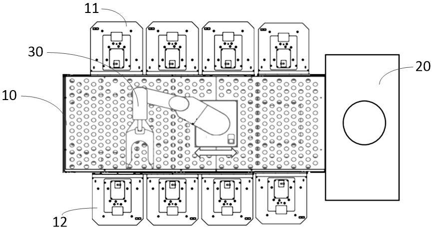
[0005] 1) When the equipment is sorting and running, the internal robot (Robot) and the mechanical arm are constantly moving, and each movement will inevitably generate eddy currents, which will lead to increased turbulence and cause particles in the equipment to fall. Falling on the wafer will affect product quality, so it is necessary to reduce the moving speed of the robot and the mechanical arm, but this will affect the production capacity of the equipment;
[0006] 2) The currently used wafer sorting equipment is a single-layer structure, and the efficiency of the equipment is low;
[0007] 3) Both OK wafers (qualified wafers) and NG wafers (unqualified wafers) in the sorting chamber are sorted in the same chamber environment, contacting the same robotic arm, there is a risk of cross-contamination;
[0008] 4) Currently used wafer sorting equipment usually has 8 to 10 ports (loading and unloading ports), the equipment space is large, and the production line occupies a large area. At the same time, it is necessary to ensure that the cleanliness of such a large area has never been problem, difficult

Method used


Image

  • A kind of wafer sorting equipment and wafer sorting method
  • A kind of wafer sorting equipment and wafer sorting method
  • A kind of wafer sorting equipment and wafer sorting method

Examples


Embodiment Construction

[0035] In order to make the purpose, technical solutions and advantages of the embodiments of the present disclosure clearer, the technical solutions of the embodiments of the present disclosure will be clearly and completely described below in conjunction with the accompanying drawings of the embodiments of the present disclosure. Apparently, the described embodiments are some of the embodiments of the present disclosure, not all of them. Based on the described embodiments of the present disclosure, all other embodiments obtained by persons of ordinary skill in the art without creative effort fall within the protection scope of the present disclosure.

[0036] Unless otherwise defined, the technical terms or scientific terms used in the present disclosure shall have the usual meanings understood by those skilled in the art to which the present disclosure belongs. "First", "second" and similar words used in the present disclosure do not indicate any order, quantity or importan...


PUM


Abstract

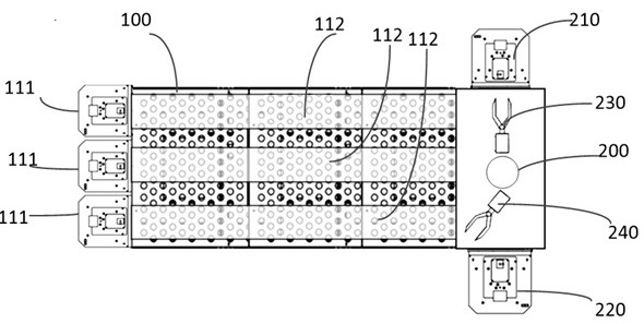
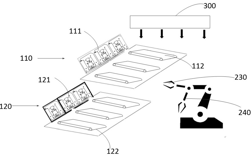
The present disclosure provides a wafer sorting equipment and a wafer sorting method, the equipment includes: a sorting chamber, including a first layer chamber and a second layer chamber, the feeding end of the first layer chamber is provided with The first feeding port, the first conveyor belt is arranged in the first floor chamber; the second feeding port is provided at the feeding end of the second layer chamber, and the second conveyor belt is arranged in the second layer chamber; A filter fan unit is arranged on the top of the filter; the calibrator unit is located at the feeding end of the sorting chamber, the calibrator unit is provided with at least a first feeding port and a second feeding port, and at least two mechanical arms are arranged inside the calibrator unit , the first robotic arm is used to transfer OK wafers from the first loading port to the first conveyor belt of the first chamber, and the second robotic arm is used to transfer NG wafers from the second loading port to the second on the second conveyor in the layer chamber. The wafer sorting equipment and the wafer sorting method provided in the present disclosure can improve environmental cleanliness during wafer sorting, reduce pollution risks, and improve efficiency.

Description

technical field [0001] The invention relates to the technical field of semiconductor production and manufacturing, in particular to a wafer sorting device and a wafer sorting method. Background technique [0002] With the rapid development of semiconductors, the requirements for the cleanliness of wafers are getting higher and higher. As the sorting equipment for wafers before shipment, the cleanliness of ShippingCompiler is particularly important. Some originally OK (qualified) wafers will also have abnormal conditions such as contamination due to wafer sorting equipment. [0003] In the related art, the main structure of the wafer sorting equipment is as follows: the equipment includes a sorting chamber, an Aligner (aligner) mechanism is provided at one end of the sorting chamber, and the front and rear sides of the sorting chamber are respectively provided with The Load port (upper port) and the Unload port (lower port) of the wafer are equipped with a robot and a mechan...

Claims


Application Information

Patent Timeline
Patent Type & Authority Patents(China)
IPC IPC(8): B07C5/36B07C5/38H01L21/67B25J9/00
CPCB07C5/362B07C5/38B07C2501/0063B25J9/0093H01L21/67271
Inventor 孙介楠
Owner XIAN ESWIN SILICON WAFER TECH CO LTD
Learn More