
3D printer print head guide mechanism

A 3D printer and guiding mechanism technology, applied in the field of 3D printing, can solve the problems of increasing production costs, affecting printing quality, and not taking into account the synchronization of printing heads, etc., to increase adjustability, eliminate fit gaps, and save production and maintenance cost effect

Active Publication Date: 2022-04-19
黎图(晋江)科技有限公司
View PDF4 Cites 0 Cited by
  • Summary
  • Abstract
  • Description
  • Claims
  • Application Information

AI Technical Summary

Problems solved by technology

[0006] To sum up, the 3D printers in the prior art do not take into account how the print head can be accurately synchronized with the drive mechanism in real time, how to realize the real-time tracking of the data information transmitted by the print head after the model slicing process, and do not take into account the data information transmitted by the drive mechanism. In the process of reaching the end of the print head, there is a fit gap in the transmission mechanism, which makes the print head unable to track the model slice data information in real time, which affects the printing quality. Machining accuracy to solve this problem, but it will inevitably increase production costs, and the maintenance of high-precision parts is also a consideration in subsequent production

Method used


Image

  • 3D printer print head guide mechanism
  • 3D printer print head guide mechanism
  • 3D printer print head guide mechanism

Examples


Embodiment Construction

[0034] The present invention will be further described below in conjunction with the examples, but the present invention is not limited in any way, and any transformation or substitution made based on the teaching of the present invention belongs to the protection scope of the present invention.

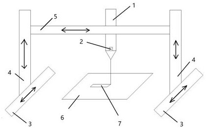
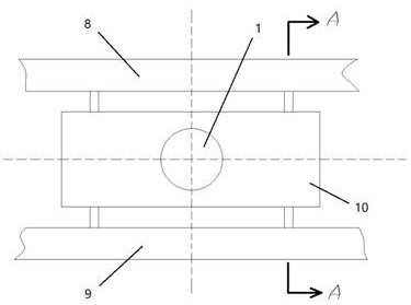
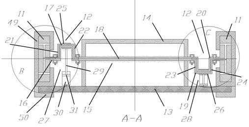
[0035] Such as figure 1 As shown, the 3D printer of the present invention includes: a printing head 1, a camera 2, a lateral guide seat 3, a vertical guide column 4, a horizontal guide rod 5 and a printing platform 6, and the camera 2 is fixedly arranged on the printing head 1 for collecting For the image data of the three-dimensional printing part 7, after it is judged that the printing of the three-dimensional printing part 7 is completed, the printing of the printing head 1 is stopped. The print head 1 is slidably arranged on the horizontal guide rod 5 through the sliding seat 10, and can slide left and right along the horizontal guide rod 5. A vertical guide column 4 is respectiv...


PUM


Abstract

In the 3D printer print head guiding mechanism of the present application, the print head is arranged on the sliding seat, and the sliding seat is sandwiched between two horizontal guide rods, and the rollers and the guide bottom plate are slid to be arranged in the horizontal guide rod, and the guide bottom plate plays the main role. Supporting function, the roller is only set to limit the sliding speed of the sliding seat, and a speed limiting mechanism is set between the roller and the sliding seat, so as to ensure that the print head can follow the driving mechanism in real time and accurately, eliminating the gap between the transmission mechanism At the same time, using the cylinder as the specific limit mechanism has a simple and novel structure.

Description

technical field [0001] The invention relates to the technical field of 3D printing, in particular to a 3D printer print head guiding mechanism. Background technique [0002] 3D printing technology is a kind of rapid prototyping technology. It establishes a three-dimensional digital model file in computer modeling software, then slices the model, and uses a printer to stack layer by layer to construct the model entity. The materials used for stacking include Powdered metal or plastic. Due to its precision, intelligence and other advantages, 3D printing technology has been widely used in aerospace, biomedical, national defense, industrial manufacturing and other fields. The nozzle of a 3D printer has a crucial impact on the quality of 3D printing. Since the nozzle needs to reciprocate on the guide rail to achieve 3D printing under the drive of the driving mechanism, the nozzle guiding device directly affects the quality of 3D printing. For example, Patent Document 1 disclose...

Claims


Application Information

Patent Timeline
Patent Type & Authority Patents(China)
IPC IPC(8): B29C64/20B29C64/227B29C64/30B33Y30/00
CPCB29C64/20B29C64/227B29C64/30B33Y30/00
Inventor 王明丹王金伟
Owner 黎图(晋江)科技有限公司
Learn More