Flap gate mechanism

A flap and material door technology, which is applied to containers, packaging, transportation and packaging, etc., can solve the problems of wear around the flap, wear of the insert, and poor sealing of the silo, and achieves good sealing performance, reduces failure rate, Easy-to-start effects

Inactive Publication Date: 2021-01-29
HEILONGJIANG INST OF PASTURAGE MECHANISATION
View PDF3 Cites 0 Cited by
  • Summary
  • Abstract
  • Description
  • Claims
  • Application Information

AI Technical Summary

Problems solved by technology

[0002] At present, most of the feed gates used in the silos of feed factories have two forms. One is the form of a sliding plate. When working, the sliding plate advances or retreats through the slide to achieve the effect of sealing or falling the feed in the silo. The disadvantage of this form is that the inserting plate will rub against the feed when it is opened and closed. As the working time goes by, the inserting plate will be continuously worn, resulting in poor sealing and material leakage. It needs to be replaced in time, which is labor-intensive and time-consuming. The other is to use the flap form, the disadvantages are: 1. This form generally uses electric control components to limit the position. After the flap is closed, the horizontal position of the flap is not easy to reach the ideal state, and it needs to be adjusted continuously, which is very prone to material leakage. 2. Because there is a gap between the flap and the side wall of the silo, in order to ensure the sealing, the processing precision of the flap is high, and the production is difficult. Moreover, after a long time of work, the periphery of the flap will be worn, resulting in a gap with the silo. The sealing is not strict, and the phenomenon of material leakage occurs. 3. The feed is located on the top of the flap, and there is no material guide device, so the power consumption of the flap is large.

Method used


Image

  • Flap gate mechanism
  • Flap gate mechanism
  • Flap gate mechanism

Examples


Embodiment Construction

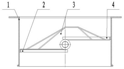
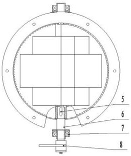
[0016] exist figure 1 and figure 2 In the structural diagram, the lower retaining ring (2) and the upper retaining ring (4) are horizontally staggered and welded on the inner wall of the material barrel (1), the flap door rotor (3) is located in the material barrel (1), and the main shaft (6) Pass through the material barrel (1) and the flap material door rotor (3) and fix it on the material barrel (1) through the bearing seat (7). At the same time, the main shaft (6) is also connected with the flap material door rotor ( 3) connected with each other, the wrench (8) is installed at one end of the main shaft (6).

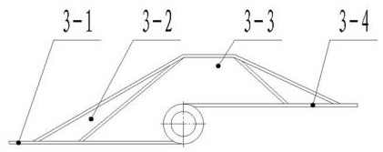
[0017] exist image 3 and Figure 4 In the structure diagram, the lower flap (3-1) and the upper flap (3-4) are welded on the bottom and top of the tube shaft (3-7) in parallel, two reinforcement plates I (3-2) and two A reinforcement plate II (3-3) is symmetrically welded on the lower flap (3-1), the tube shaft (3-7) and the upper flap (3-4), and the coaming pla...


PUM


Abstract

The invention provides a flap gate mechanism. The flap gate mechanism is composed of a charging barrel, a lower retainer ring, a flap gate rotor, an upper retainer ring, a key, a spindle, a bearing seat and a wrench. The upper retainer ring and the lower retainer ring are correspondingly 5mm-wide arc-shaped steel plates and are horizontally welded to the inner wall of the charging barrel in a staggered manner, the flap gate rotor is positioned in the charging barrel, and the spindle penetrates through the charging barrel and the flap gate rotor and is fixed to the charging barrel through the bearing seat. Meanwhile, the spindle is further connected with the flap gate rotor through the key, and the wrench is arranged at one end of the spindle. Before work, the flap gate rotor is horizontally placed, feed is sealed, during work, the wrench is started, the spindle rotates clockwise, the flap gate rotor is driven by the key to rotate clockwise, the feed located on the flap gate rotor slides down continuously, and when the flap gate rotor rotates clockwise to 90 degrees, a feed falling channel is completely opened, and the feed falls through the charging barrel. After the work is finished, the wrench is started, so that the flap gate rotor rotates anticlockwise until the flap gate mechanism is closed again.

Description

technical field [0001] The invention belongs to the technical field of feed machinery, and in particular relates to a flap material door mechanism applied to a silo of a feed factory. Background technique [0002] At present, most of the feed gates used in the silos of feed factories have two forms. One is the form of a sliding plate. When working, the sliding plate advances or retreats through the slide to achieve the effect of sealing or falling the feed in the silo. The disadvantage of this form is that the inserting plate will rub against the feed when it is opened and closed. As the working time goes by, the inserting plate will be continuously worn, resulting in poor sealing and material leakage. It needs to be replaced in time, which is labor-intensive and time-consuming. The other is to use the flap form, the disadvantages are: 1. This form generally uses electric control components to limit the position. After the flap is closed, the horizontal position of the flap ...

Claims


Application Information

Patent Timeline
Patent Type & Authority Applications(China)
IPC IPC(8): B65D88/28B65D90/66
CPCB65D88/28B65D90/66
Inventor 李爱华王敦军周凤波王宇张伯韧冯骥强董德军陈海霞吴建华何占松李洪德
Owner HEILONGJIANG INST OF PASTURAGE MECHANISATION
Why Eureka
Try Eureka