Electric winch equipment

一种电动绞盘、设备的技术,应用在机械设备、机械驱动离合器、连轴器和制动器的组合等方向,能够解决损坏、三级太阳轮与二级行星架宽度不够、绞盘无法正常使用等问题,达到提高使用效果、制动效果好的效果

Active Publication Date: 2021-01-29
ZHEJIANG RUNVA MECHANICAL & ELECTRICAL
View PDF8 Cites 0 Cited by
  • Summary
  • Abstract
  • Description
  • Claims
  • Application Information

AI Technical Summary

Problems solved by technology

But when the user forgets to pull the twisted rope, and when the elastic recovery force of the compression spring at the coupling becomes smaller after long-term use, the speed at which the third-stage sun gear enters the second-stage planetary carrier becomes slower. When the motor drives the inner teeth of the second-stage planet carrier to contact the outer teeth of the entering third-stage sun gear and start transmission, it is very likely that the third-stage sun gear has not been inserted in place; because the third-stage sun gear and the second-stage planetary There is pressure in the meshing of the teeth between the racks to generate friction. The insufficient thrust of the compression spring will inevitably lead to insufficient meshing width between the third-stage sun gear and the second-stage planetary carrier. If this state is used for a long time, the third-stage sun gear and the second-stage planet carrier The teeth of the planet carrier must be damaged, which will cause the winch to be unable to use normally

Method used


Image

  • Electric winch equipment
  • Electric winch equipment
  • Electric winch equipment

Examples


Embodiment Construction

[0039]Hereinafter, the present invention will be described with reference to the accompanying drawings; however, it should be understood that the structural proportions in the accompanying drawings are only exemplary, and are not intended to limit the scope of the present disclosure.

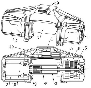
[0040]An electric winch equipment, such asfigure 1 As shown, it includes an outer shell 49, the upper side of the outer shell 49 is equipped with an electronic control module 1, the left end of the outer shell 49 is equipped with a motor module 2 and the right end is equipped with a reduction module and a clutch 4, and the lower middle of the outer shell 49 is equipped with Drum 3, the motor 10 in the motor module 2 drives the transmission shaft 8 in the drum 3 to rotate through the braking unit 9. The transmission shaft 8 drives the drum 3 to rotate through the reduction module, and the clutch 4 controls the axial movement of the transmission shaft 8; The module consists of a first-stage reduction compo...


PUM


Abstract

The invention belongs to the field of winches, and particularly relates to electric winch equipment. The electric winch equipment comprises an electric control module, a motor module, a roller, a clutch, a first-stage speed reduction assembly, a second-stage speed reduction assembly, a third-stage speed reduction assembly, a transmission shaft and a brake unit. A pressure sensor can identify whether a third-stage sun gear and a second-stage planet carrier are completely engaged or not; and after the third-stage sun gear is completely engaged with the second-stage planet carrier, a winch can benormally used only when a motor is started. By designing a friction block A and a friction block B to conduct friction braking with a friction ring A and a friction ring B respectively, braking is established between the transmission shaft and the friction ring at the position of a support and between the transmission shaft and the friction ring at the position of the roller, and a better brakingeffect is achieved. When a coupling A and a coupling B generate relative motion, a rectangular spring deforms to generate friction with the friction block A and the friction block B, but the heat generated by the friction is very small, so that the influence on the failure of the rectangular spring can be neglected, and the service life of the rectangular spring can be prolonged.

Description

Technical field[0001]The invention belongs to the field of winches, and in particular relates to an electric winch equipment.Background technique[0002]At present, in the current field of winches, the braking unit in the winch is to establish a brake between the intermediate drive shaft and the friction ring at the bracket, or between the intermediate drive shaft and the drum; The company’s winch brake scheme is to brake the intermediate drive shaft with the drum; through innovative improvements to the brake unit, the intermediate drive shaft can be braked between the friction ring and the drum at the bracket respectively, and achieve better Good braking effect.[0003]In addition, in the current field of winches, the principle of the power connection or clutch between the deceleration assembly and the intermediate drive shaft in the winch is: the clutch is realized by changing the meshing relationship between the three-stage sun gear and the two-stage planet carrier. When the sun gear...

Claims


Application Information

Patent Timeline
Patent Type & Authority Applications(China)
IPC IPC(8): B66D1/74B66D1/14B66D5/08F16D47/02F16D67/02F16D11/16
CPCB66D1/14B66D1/7447B66D1/7484B66D5/08F16D11/16F16D47/02F16D67/02F16D2011/004
Inventor 俞芷琳戴林吉张小彬叶岭
Owner ZHEJIANG RUNVA MECHANICAL & ELECTRICAL
Why Eureka
Try Eureka