
A lower chord reinforced steel truss girder inspection vehicle lifting platform

A technology for lifting platforms and inspection vehicles, which is applied in the direction of lifting devices and safety devices for lifting equipment, etc. It can solve the problems of complex structure of stiffening parts, large lifting range, and self-heavy lifting mechanism, so as to achieve firm and reliable connection structure and good safety , the effect of simple structure

Active Publication Date: 2022-03-29
ZHUZHOU TIMES NEW MATERIALS TECH
View PDF0 Cites 0 Cited by
  • Summary
  • Abstract
  • Description
  • Claims
  • Application Information

AI Technical Summary

Problems solved by technology

The stiffening part of this type of structure is complicated in structure and has a lot of interference. It is not suitable for direct laying of the track and inspection with an inspection vehicle. It is necessary to use a lifting platform for inspection.
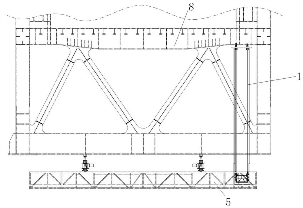
Existing lower chord inspection vehicles of steel truss girders generally use scissor mechanism or mast lifting mechanism to inspect the internal structure of steel truss girders, but the height of the stiffening part of variable section bottom chord stiffened continuous steel truss girder exceeds the working limit of scissor mechanism or mast lifting mechanism. Even if the height of some stiffening parts does not exceed the working limit, the self-weight of the lifting mechanism will be too large due to the large lifting range, which is not suitable for inspection vehicles.

Method used


Image

  • A lower chord reinforced steel truss girder inspection vehicle lifting platform
  • A lower chord reinforced steel truss girder inspection vehicle lifting platform
  • A lower chord reinforced steel truss girder inspection vehicle lifting platform

Examples


Embodiment Construction

[0026] The present invention will be described in further detail below in conjunction with the accompanying drawings and specific embodiments.

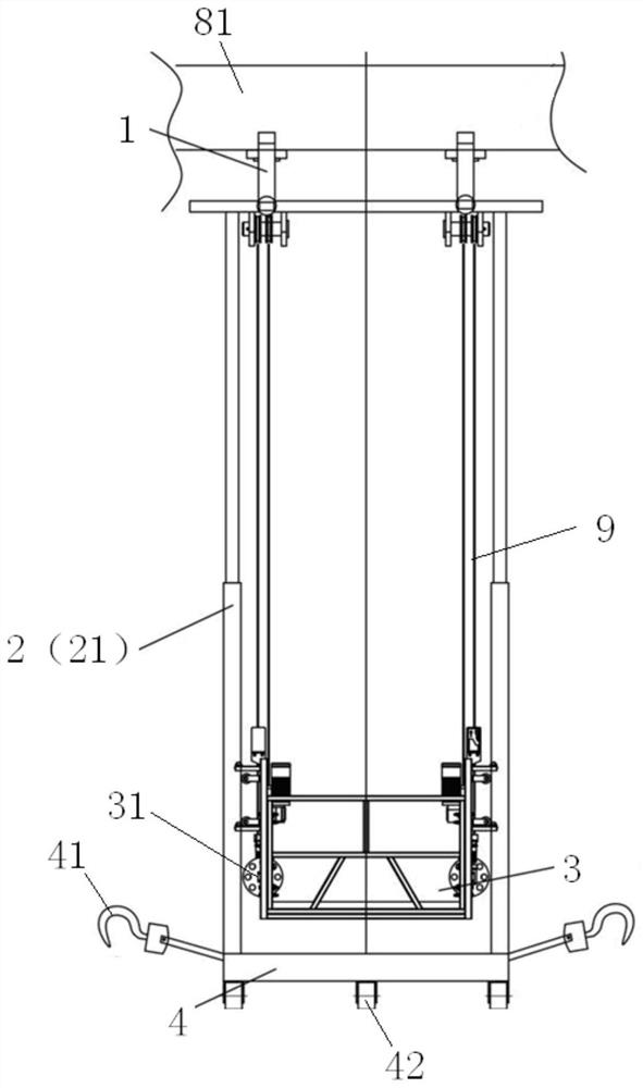
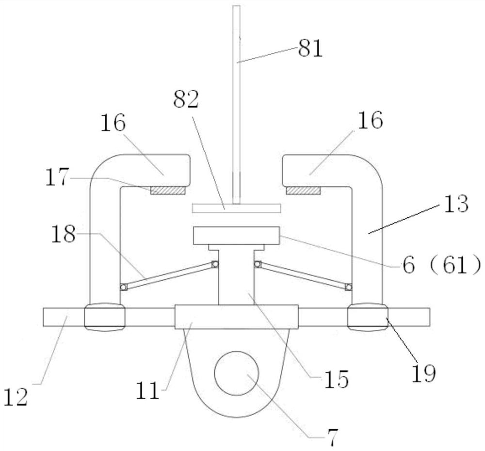
[0027] Such as Figure 1 to Figure 6 As shown, the lower chord stiffened steel truss girder inspection car lifting platform of this embodiment includes a gripper platform 1, a lifting mechanism 2, a hanging basket 3 and a base 4, the base 4 is movably arranged on the inspection car 5, and the gripper platform 1 It includes a connecting plate 11, a first mounting shaft 12, a pair of grasping arms 13, and a second mounting shaft 14. The first mounting shaft 12 is horizontally installed on the connecting plate 11, and the second mounting shaft 14 is erected on the connecting plate 11. A pair of The grasping arm 13 is movably installed on the first installation shaft 12 and is separately arranged on both sides of the second installation shaft 14. The second installation shaft 14 is provided with a second sliding sleeve 15, and the top of ...


PUM


Abstract

The invention discloses a lower chord-stiffened steel truss girder inspection vehicle lifting platform, which includes a gripping platform, a lifting mechanism, a hanging basket and a base, the base is movably arranged on the inspection vehicle, and the lifting mechanism is used to drive the gripping platform to go up and down. The hand platform includes a connection plate, a first installation shaft, a pair of gripping arms, and a second installation shaft. The first installation shaft is installed horizontally on the connection plate, and the second installation shaft is erected on the connection plate. On the first installation shaft and separately arranged on both sides of the second installation shaft, the second installation shaft is provided with a second sliding sleeve, the top of the second sliding sleeve is provided with a magnetic adsorption piece, the second sliding sleeve and the two grasping arms Connected by a connecting piece, the gripping arm is provided with a gripper, the grippers of the two gripping arms are set inward, the gripper is located above the magnet adsorption piece, the connecting plate is provided with a hanging point, and the hanging basket is hung on the hanging point . The invention realizes the connection through the magnetic adsorption, and the connection is firm and reliable, has good safety, has double protection functions, and has a small self-weight of the lifting mechanism.

Description

technical field [0001] The invention relates to bridge inspection equipment, in particular to a lower chord stiffened steel truss girder inspection vehicle lifting platform. Background technique [0002] With the improvement of materials and construction technology and the requirement of bridge height limit in some areas, the application of variable section lower chord stiffened steel truss girders is becoming more and more extensive. The stiffening part of this type of structure is complicated in structure and has a lot of interference, so it is not suitable for direct laying of the track and inspection with an inspection vehicle, and it is necessary to borrow a lifting platform for inspection. Existing lower chord inspection vehicles of steel truss girders generally use scissor mechanism or mast lifting mechanism to inspect the internal structure of steel truss girders, but the height of the stiffening part of variable cross-section lower chord stiffened continuous steel t...

Claims


Application Information

Patent Timeline
Patent Type & Authority Patents(China)
IPC IPC(8): B66F11/04B66F13/00B66F17/00
CPCB66F11/04B66F13/00B66F17/006
Inventor 管峰刘军李文斌梅仕伟
Owner ZHUZHOU TIMES NEW MATERIALS TECH
Learn More