Strain pressure sensor

A pressure sensor and strain gauge technology, applied in the field of sensors, can solve the problems of complex processing of strain pressure sensors, low sensor precision, and low sensor, and achieve the effects of simple structure, high measurement accuracy, and low overall height

Pending Publication Date: 2021-01-29
深圳市鑫精诚科技有限公司
View PDF1 Cites 2 Cited by
  • Summary
  • Abstract
  • Description
  • Claims
  • Application Information

AI Technical Summary

Problems solved by technology

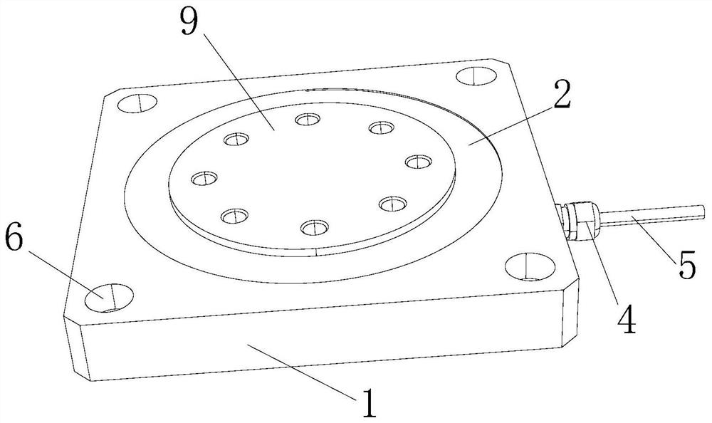
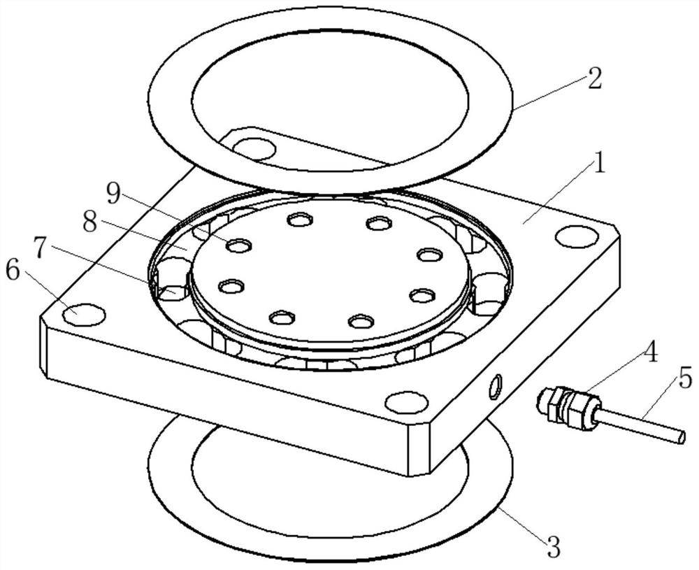
[0005] The purpose of the present invention is to provide a strain pressure sensor, which uses a patch beam designed with an annular groove to connect the bearing platform, and the two sides of the patch beam are arc transitions, which can transmit force smoothly during the force transmission process, and the patch beam Strain gauges are pasted on the upper surface to form a Wheatstone bridge. This structure has a strong ability to resist eccentric loads and lateral loads, and is more economical to process. The overall height of the sensor is low, the measurement range is large, and the advantages of high precision solve the problem of existing strain pressure. The processing of the sensor is complicated, and often requires multiple processes to complete the processing of the sensor, and the accuracy of the sensor is low, which will cause a problem of high eccentric load difference when detecting the pressure of the entire extrusion process

Method used


Image

  • Strain pressure sensor
  • Strain pressure sensor

Examples


Embodiment Construction

[0020] In order to make the object, technical solution and advantages of the present invention clearer, the present invention will be further described in detail below in conjunction with the accompanying drawings and embodiments. It should be understood that the specific embodiments described here are only used to explain the present invention, not to limit the present invention.

[0021] The implementation of the present invention will be described in detail below in conjunction with specific embodiments.

[0022] In the drawings of this embodiment, the same or similar symbols correspond to the same or similar components; The indicated orientation or positional relationship is based on the orientation or positional relationship shown in the drawings, and is only for the convenience of describing the present invention and simplifying the description, rather than indicating or implying that the referred device or element must have a specific orientation, or in a specific orien...


PUM


Abstract

The invention relates to the technical field of sensors, and discloses a strain pressure sensor which comprises an elastomer, a patch beam is arranged in the middle of the elastomer, a bearing table is connected with the middle of the patch beam, a strain gauge is attached to the upper surface of the patch beam, and the strain gauge and the patch beam form a Wheatstone bridge; a cable is arrangedon one side of the elastomer, one end of the cable is connected with the Wheatstone bridge, and the other end of the cable is connected with an external display device. The patch beam with the annulargroove design is adopted to be connected with the bearing table, the two sides of the patch beam are in circular arc transition, force can be stably transmitted in the force transmission process, thestructure is high in eccentric load resistance and lateral load resistance, machining is more economical, and the sensor is low in overall height, large in measurement range and high in precision.

Description

technical field [0001] The invention relates to the technical field of sensors, in particular to a strain pressure sensor. Background technique [0002] With the rapid development of new energy, the demand for new energy batteries is also increasing, but its complex production environment requirements (high temperature, high humidity and corrosive environment in the production workshop), the more automation requirements on the production line In such an environment, it is required to control various production parameters, especially the control of the extrusion force during the extrusion process of the pouch battery has a great impact on the quality of the battery. At present, it is necessary to constantly Monitor the force value and detect the pressure of the entire extrusion process at any time, so the force sensor is installed on the chemical forming machine, but due to the particularity of the equipment, it is also necessary to quickly check the sensor online in the work...

Claims


Application Information

Patent Timeline
Patent Type & Authority Applications(China)
IPC IPC(8): G01B7/16G01L1/16
CPCG01B7/16G01L1/16
Inventor 吴神剑沈力吴美贞
Owner 深圳市鑫精诚科技有限公司
Why Eureka
Try Eureka