
Chip testing device

A chip testing and chip technology, applied in the direction of measuring devices, electronic circuit testing, measuring electricity, etc., can solve the problems of testing printed circuit boards beyond the standard warping, machine time loss, etc.

Pending Publication Date: 2021-01-29
SINO IC TECH
View PDF0 Cites 0 Cited by
  • Summary
  • Abstract
  • Description
  • Claims
  • Application Information

AI Technical Summary

Problems solved by technology

[0004] The purpose of the present invention is to provide a chip testing device to solve the problem of super-standard warping of the printed circuit board, thereby reducing its influence on the test results, avoiding machine time loss and production delay

Method used


Image

  • Chip testing device

Examples


Embodiment Construction

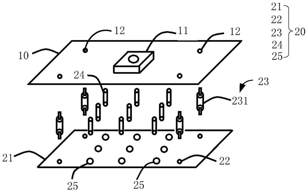
[0027] A chip testing device of the present invention will be further described in detail below. The invention will now be described in more detail with reference to the accompanying drawings, in which preferred embodiments of the invention are shown, it being understood that those skilled in the art may modify the invention described herein and still achieve the advantageous effects of the invention. Therefore, the following description should be understood as the broad knowledge of those skilled in the art, but not as a limitation of the present invention.

[0028] In the interest of clarity, not all features of an actual implementation are described. In the following description, well-known functions and constructions are not described in detail since they would obscure the invention with unnecessary detail. It should be appreciated that in the development of any actual embodiment, numerous implementation details must be worked out to achieve the developer's specific goals...


PUM


Abstract

The invention provides a chip testing device, which is used for testing the electrical performance of a chip to be tested. The device comprises a testing printed circuit board comprising a front surface and a back surface which are oppositely arranged, wherein a chip testing socket is fixed on the front surface, and the chip testing socket is used for inserting a to-be-tested chip; and a supporting structure which is fixed and connected to the back surface of the test printed circuit board and is used for supporting the chip test socket from the back surface. According to the invention, the problem of over-standard warping of the test printed circuit board is solved through the support structure, the influence of the over-standard warping on the test result is reduced, and the machine-hourloss and the production delay are avoided.

Description

technical field [0001] The invention relates to the field of chip testing, in particular to a chip testing device. Background technique [0002] When testing the electrical performance of the test chip on the printed circuit board, it is necessary to automatically put the chip to be tested into the chip test socket on the test printed circuit board by a manipulator. The chip test socket usually uses a Pogo Pin test socket. The process of putting the chip to be tested into the chip test socket is to put each pin of the chip into the corresponding pogo pin, and each pin is put into the pogo pin. The pressure on the pogo pins is about 30g when it is medium, and the number of pins of the chip to be tested may be thousands, so when the thousands of pins are put into the pogo pins, the total pressure on all the pogo pins The pressure can reach tens of kilograms, and these weights will concentrate on the test socket for testing the printed circuit board. [0003] During the high-...

Claims


Application Information

Patent Timeline
Patent Type & Authority Applications(China)
IPC IPC(8): G01R31/28
CPCG01R31/2886G01R31/2891G01R31/2887
Inventor 张寅凌俭波叶建明季海英祁红飞吴勇佳
Owner SINO IC TECH
Learn More