Armor stripping device for armored optical fiber and using method thereof
A stripping device and optical fiber technology, applied in the direction of light guides, optics, optical components, etc., can solve the problems of low error tolerance, laborious, time-consuming, etc., and achieve the effects of saving labor costs, simplifying stripping work, and being easy to manufacture and process
- Summary
- Abstract
- Description
- Claims
- Application Information
AI Technical Summary
Problems solved by technology
Method used
Image
Examples
Embodiment 1
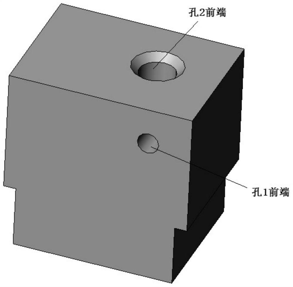
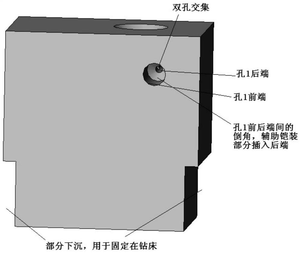
[0029] Such as Figure 5 As shown, the device fixing block is used to carry the fiber insertion hole and cut the positioning hole, and fix the whole device at the designated position. The device fixing block is a cuboid structure, and machine tool fixing clip grooves are arranged on both sides of the cuboid structure, and the machine tool fixing clip grooves are used to fix the armor stripping device at a designated position.
[0030] Preferably, the clamping groove of the machine tool is a ladder structure formed after removing two cuboids; in this structure, the upper part is a larger cuboid, the lower part is a smaller cuboid, and the front plane and rear part of the two cuboids The planes are coplanar; the carrying optical fiber insertion hole and the cutting positioning hole are respectively arranged on a larger cuboid.
Embodiment 2
[0032] A sliding groove and a sliding block are arranged on the device fixing block, a scale is arranged on the sliding groove, and a fixing buckle is arranged on the corresponding scale. The sliding groove is vertically arranged on the left plane of the device fixing block, the slider can slide up and down on the sliding groove, and the buckle on the sliding groove can fix the slider. By sliding the scale on the groove, the position of the slider can be adjusted at any time. The optical fiber insertion hole is arranged on the slider, and the optical fiber insertion hole intersects with the resection positioning hole to form a space intersecting gap. When using the device, first open the buckle on the sliding groove, slide the slider to the specified position, and determine the specific position of the slider through the scale on the sliding groove; when the slider slides to the specified position, Close the buckle on the sliding groove to fix the slider without relative slid...
Embodiment 3
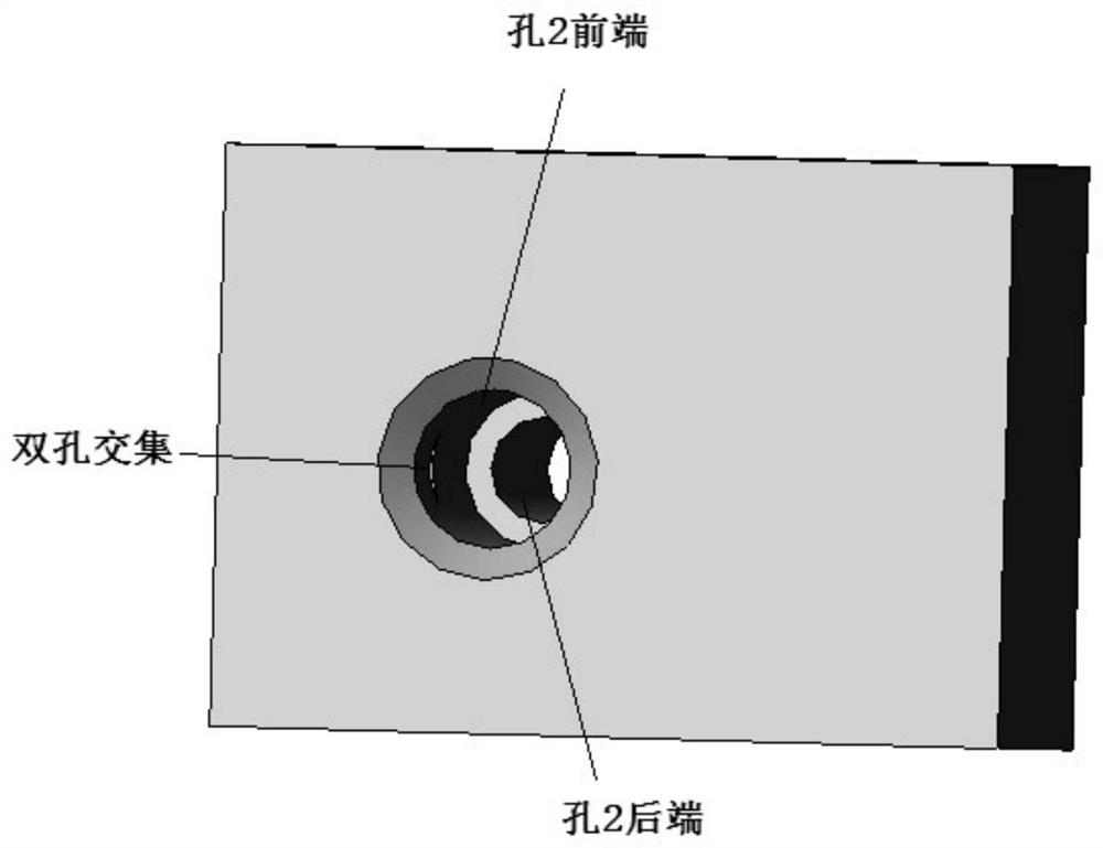
[0037] A kind of armor stripping device of armored optical fiber, such as image 3 As shown, the optical fiber insertion hole provided on the device is composed of a front hole and a rear hole, and the diameter of the front hole is larger than that of the rear hole. The front hole is used to fix the fiber with a complete outer protective layer; the back hole is used to fix the fiber that needs to be stripped. When using the armor stripping device, align the optical fiber to be stripped with the optical fiber insertion hole, and fix the optical fiber when the optical fiber is inserted into the designated position.
[0038] Preferably, a fixing ring is used to fix the optical fiber in the fiber insertion hole; the fixing ring is a ring structure, the diameter of the outer ring is the same as the diameter of the front hole of the fiber insertion hole, and the diameter of the inner ring is larger than the diameter of the armored optical fiber ; There are at least two optical fibe...
PUM
| Property | Measurement | Unit |
|---|---|---|
| Width | aaaaa | aaaaa |
Abstract
Description
Claims
Application Information
 - R&D
- Intellectual Property
- Life Sciences
- Materials
- Tech Scout
- Unparalleled Data Quality
- Higher Quality Content
- 60% Fewer Hallucinations
Browse by: Latest US Patents, China's latest patents, Technical Efficacy Thesaurus, Application Domain, Technology Topic, Popular Technical Reports.
© 2025 PatSnap. All rights reserved.Legal|Privacy policy|Modern Slavery Act Transparency Statement|Sitemap|About US| Contact US: help@patsnap.com


