Method for pre-embedding sensing line in channel cover plate

A sensing line and cover plate technology, which is applied in the field of pre-embedded sensing lines in the trench cover plate, can solve the problems of being easily damaged and not easy to detect the damage of the trench cover plate in time, and achieve the effect of improving sensitivity

Active Publication Date: 2021-01-29
北京思迈特科技有限公司
View PDF8 Cites 0 Cited by
  • Summary
  • Abstract
  • Description
  • Claims
  • Application Information

AI Technical Summary

Problems solved by technology

The existing trench cover plates are made of cement reinforced concrete and polymer composite materials, etc., but because they are exposed to the outside for a long time and are subjected to mechanical forces such as rolling, handling, and prying for a long time, they are very easy to be damaged, and the work is difficult. It is not easy to detect the damage of the trench cover in time because the personnel are regularly overhauled; in order to detect the damage of the trench cover, CN110095504A and CN111089716A disclose a trench cover that can be used to monitor the damage of the trench cover and open state

Method used


Image

  • Method for pre-embedding sensing line in channel cover plate
  • Method for pre-embedding sensing line in channel cover plate
  • Method for pre-embedding sensing line in channel cover plate

Examples


Embodiment 1

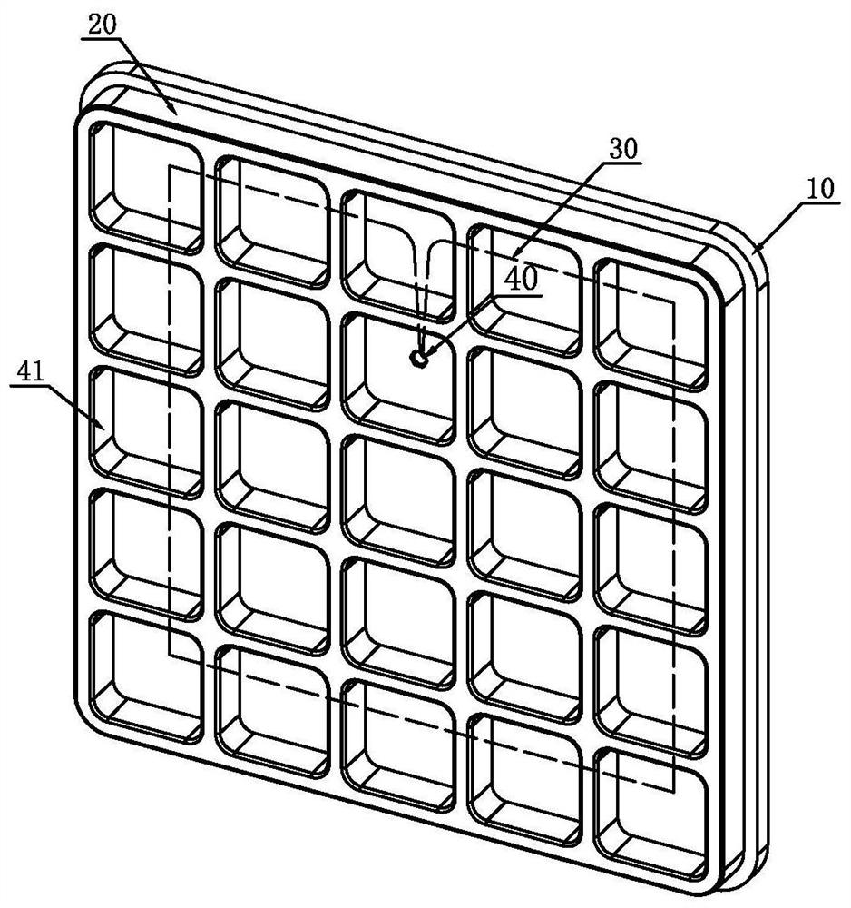
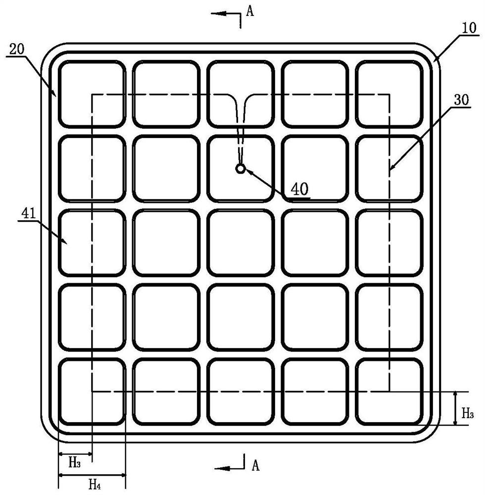
[0043] The first embodiment of the present invention provides a method for pre-embedding sensing lines in the trench cover plate, such as figure 1 and figure 2 As shown, the channel cover plate includes a cover plate upper part 10, a cover plate lower part 20, a sensing line 30 embedded in the upper part of the cover plate, connected with the sensing line 30 and lowered from the cover plate upper part 10. The sensing line joint 40 protruding from the end surface and the reinforcement mesh (not shown in the figure) embedded in the lower part 20 of the cover plate, the reinforcement mesh is composed of a plurality of reinforcement grids; the reinforcement mesh connects the lower part 20 of the cover plate Divided into a plurality of hollow grids 41, the hollow grids are preferably square structures, such as Figure 4 As shown, the sensing line joint 40 is located in the hollow grid, and the distance from the surrounding of the hollow grid is 3cm, which is convenient for constr...

Embodiment 2

[0053] The second embodiment of the present invention provides a method for pre-embedding sensing wires in the trench cover plate. The trench cover plate is based on the first embodiment, and the distance between the sensing line 30 and the top surface of the top 10 of the cover plate is the distance H 1 7 / 10 cover plate upper thickness H 2 , the sensing line 30 is located at the outermost hollow grid length H around the lower part of the cover plate 4 at the 3 / 5 position; the cross-sectional diameter of the sensing line is 1mm, and the method comprises the following steps:

[0054] 1) Take the lower mold of the cover plate with blind holes and a plurality of grooves arranged horizontally and vertically on the top surface; the structural diagram of the lower mold of the cover plate is as follows: Figure 6 As shown, the grid size formed by the groove matches the size of the reinforcement grid;

[0055] 2) Place the steel mesh in the groove of the mold under the cover plate;...

Embodiment 3

[0062] The third embodiment of the present invention provides a method for pre-embedding sensing wires in the trench cover plate. The trench cover plate is based on the first embodiment, and the distance between the sensing line 30 and the top surface of the top 10 of the cover plate is the distance H 1 4 / 5 cover upper thickness H 2 , the sensing line 30 is located at the outermost hollow grid length H around the lower part of the cover plate 4 at the 2 / 5 position; the cross-sectional diameter of the sensing line is 1mm, and the method comprises the following steps:

[0063] 1) Take the lower mold of the cover plate with blind holes and a plurality of grooves arranged horizontally and vertically on the top surface; the structural diagram of the lower mold of the cover plate is as follows: Figure 6 As shown, the grid size formed by the groove matches the size of the reinforcement grid;

[0064] 2) Place the steel mesh in the groove of the mold under the cover plate;

[006...


PUM


Abstract

The invention provides a method for pre-embedding a sensing line in a channel cover plate. The method comprises the following steps: taking a cover plate lower mold with a blind hole; placing a part of cover plate material on the cover plate lower mold, reserving the position of the blind hole, and flattening to form a first layer of cover plate matrix; placing the sensing line on the first layerof cover plate substrate, and plugging a sensing line connector into the blind hole; and paving the other part of the cover plate material to form a second layer of cover plate matrix, and paving thesecond layer of cover plate matrix on the first layer of cover plate matrix and the sensing lines. The sensing line pre-buried by the method has very high detection sensitivity.

Description

technical field [0001] The invention belongs to the technical field of pre-embedded sensing lines, in particular to a method for pre-embedding sensing lines in a trench cover plate. Background technique [0002] There are a large number of cable and optical cable trenches in power generation facilities. In order to ensure the safety of cables and optical cables in the trenches, avoid aging caused by direct sunlight, and prevent rain, dust, and debris from falling into the trenches, protection must be set up on the trenches. Functional trench cover. The existing trench cover plates are made of cement reinforced concrete and polymer composite materials, etc., but because they are exposed to the outside for a long time and are subjected to mechanical forces such as rolling, handling, and prying for a long time, they are very easy to be damaged, and the work is difficult. It is not easy to detect the damage of the trench cover in time because the personnel are regularly overhau...

Claims


Application Information

Patent Timeline
Patent Type & Authority Applications(China)
IPC IPC(8): H02G9/02H02G1/00G02B6/50
CPCH02G9/025H02G1/00G02B6/50
Inventor 商小龙曾维鲁
Owner 北京思迈特科技有限公司
Why Eureka
Try Eureka